Abstract
A better understanding of the open-circuit voltage ( ) related losses in organic solar cells (OSCs) is desirable in order to assess their photovoltaic performance. We have derived
  as a function of charge carrier mobilities (
 and
and ) for organic and hybrid solar cells by optimizing the drift-diffusion current density. The
  thus obtained depends on the energy difference between the highest occupied molecular orbital (HOMO) level and the quasi-Fermi level of holes of the donor material and on the ratio of the electron (
 ) and hole (
 ) mobilities in the blend. It is found that the
  increases with the increase of the mobility ratio
 . The most loss in
  is contributed by the energetics of the donor and acceptor materials.
charge carrier mobility, donor-acceptor, open-circuit voltage, organic solar cells, quasi-fermi levels
Introduction
Research interest in organic solar cells (OSCs) is currently on the increase mainly because of their cost effectiveness, flexibility, easy fabrication techniques, large scale production and the potential integration of OSCs into a wide variety of devices [1-4]. The development of new materials for photovoltaic applications coupled with device optimization has led to a dramatic increase in OSCs’ performance in recent years [5]. A major research focus now lies in finding ways for further optimization of the power conversion efficiency (PCE), guided by a deeper understanding of the fundamental processes that influence the photovoltaic properties of OSCs [6]. The following four processes of OSCs and organic hybrid solar cells (OHSCs) make them remarkably different from their inorganic counterparts: i) photon absorption and exciton generation; ii) diffusion of excitons to the donor acceptor (DA) interface; iii) dissociation and charge separation at the interface; and iv) carrier collection by the electrodes [1,2]. These four processes have to be sufficiently efficient to reduce or eliminate energy losses leading to reduction in the short-circuit current density and open-circuit voltage
 , and hence, reduction in the power conversion efficiency of OSCs and OHSCs.
The current density in the drift-diffusion model is a function of both the electrical and chemical potentials gradients, denoted by
 and
and , respectively. In OSCs,
  is negligible because there is no built-in electric field like the one in inorganic solar cells due to the property of p-n junction [7]. Therefore, in OSCs and OHSCs
  depends mainly on the gradient of the chemical potential which is a function of
  as shown below. Thus,
  becomes a function of
  and by optimizing
 with respect to
  one can determine the optimal value of
  corresponding to
 .
.
It is established that the  of OSCs [8-11] depends on the energy difference between the highest occupied molecular orbital (HOMO) of the donor material and lowest unoccupied molecular orbital (LUMO) of the acceptor material or the conduction band of the inorganic nanoparticle in the case of OHSCs [12]. In addition, simulation [5,6] and experimental [13-15] works show that charge transport have effect on PCE of OSCs and a detailed analysis of bulk heterojunction organic solar cells reveals that low
  is the main factor limiting this efficiency [9]. This implies that the
  of an OSC depends on the transport properties of the charge carrier in the material, which has not yet been studied adequately.
In this work, we have derived an analytical expression for  by optimizing the drift-diffusion current density
 . The
. The  thus obtained depends explicitly on the electron and hole mobilities and donor and acceptor HOMO and LUMO energy levels. In a previous study (Wurfel et al., 2015), the effective carrier mobility
  is used to define the external voltage applied across an OSC, however in our approach the concept of the effective mobility is not used. Instead, it is found that the
  depends on the ratio of the electron (
 ) to hole (
 ) mobility such that if the ratio
  increases the
  also increases.
Derivation of Open-Circuit Voltage ( )
)
The open-circuit voltage is given by the energy difference between the electron and hole quasi-Fermi levels (Gregg, 2003)
 , (1)
, (1)
In OSCs and OHSCs the open-circuit voltage is also related to the HOMO energy level of the donor and the LUMO energy level of the acceptor
 as [16]:
 , (2)
, (2)
where is an empirical value representing energy losses in transporting charge carriers to the electrodes.
According to the drift-diffusion model the total current density J in a semiconductor under bias can be written as the sum of the electron and hole current densities, given by [17]:
 , (3)
, (3)
where  is the electron current density and
  is the hole current density . Here
  is the electron (hole) density,
  is the electron (hole) mobility, and
 is the gradient of the electron (hole) quasi-Fermi level.
The charge-carrier densities  and
and of electrons and holes inside the active layer are, respectively, given as [18]
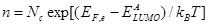 , (4)
, (4)
and
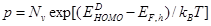 , (5)
, (5)
where is the effective density of states for the LUMO (HOMO) of acceptor (donor) material and
  is the energy of the corresponding Fermi levels. Using equations (1)-(5), the total current density in (3) can be written as a function of
  as:
as:
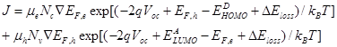 , (6)
, (6)
The total current density in equation (6) can be optimized with respect to
  as
as  , which gives:
 , (7)
, (7)
In OSCs the chemical potential energy gradient  drives the electrons and holes in the opposite direction (Gregg, 2003), this explains the significance of the minus sign on the left hand side of equation (7) the minus sign is dropped from here onwards for convenience.
Multiplying both sides of equation (7) by 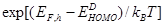 we get:
 , (8)
, (8)
where  is the effective band gap or the DA interface energy gap. Rearranging equation (8) we obtain
  as:
as:
 , (9)
, (9)
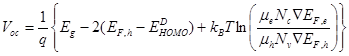
Following earlier works [5, 18] {Wagenpfahl, 2010 #121;Wurfel, 2015 #110} we assume  and
and  which gives;
 where
where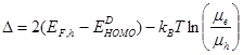 , (10)
Here  is the energy loss contributed by the energetic (first term) and charge transport (second term)
Results
We have used equation (10) to calculate  in several donor-acceptor (DA) materials listed in Table 1. The input parameters required for each DA in the calculations are also listed in Table 1. In addition, for calculating
  from equation (10) we need the values of the energy of the donor HOMO (
 ) and acceptor LUMO (
 ) which are listed in Table 2. It may be noted that following [18] we have used
  eV in equation (10) for all DA materials used in Table 1 and 2. Using these input parameters the calculated values of
  are listed in Table 2 along with their experimental values obtained for these materials. According to Table 2, the calculated
  values are in reasonable agreement with those obtained experimentally.
Entry |
Active Layer |
 (cm2V-1s-1) (cm2V-1s-1)
|
 (cm2V-1s-1) (cm2V-1s-1)
|

|
Ref. |
OSC |
PTB7:PCBM
|
1.0x10⁻³ |
2.0x10⁻⁴ |
5.0 |
[20] |
OSC |
PCDTBT:PCBM |
2.9x10⁻³ |
3.0x10⁻⁵ |
96.7 |
[21]
|
OSC |
P3HT:PCBM |
x10-3 |
x10-4 |
10.0 |
[19] |
OSC |
MDMOPPV: PCBM
|
x10-3 |
x10-4 |
10.0 |
[19] |
OSC |
PBDTBDD:Bis-PCBM |
9.6x10⁻⁵ |
1.3x10⁻⁴ |
0.7 |
[10] |
OSC |
PBDTBDD:PCBM |
8.8x10⁻⁴ |
1.4x10⁻³ |
0.6 |
[10] |
OSC |
P3HT: Bis-PCBM |
9.6x10⁻⁵ |
1.0x10⁻⁴ |
1.0 |
[10] |
OSC |
MEHPPV: PCBM |
x10-3 |
x10-6 |
1000.0 |
[25] |
OSC |
Si-PCPDTBT:PCBM
|
2.5x10⁻⁴ |
3.0x10⁻⁵ |
8.3 |
[22] |
H |
MDMOPPV:nc-ZnO
|
2.8x10⁻⁵ |
5.5x10⁻⁶ |
5.1 |
[23] |
H |
P3HT: Si-NCs
|
x10-3 |
x10-3 |
1.0 |
[24] |
Table 1. Input values for calculating  with donor –accepter materials forming the active layer, electron mobility
  , hole
  mobility, mobility ratio P
According to equation (10) the

increases if the ratio

, that means, when the electron mobility is higher than the hole mobility as shown in Figure 1. In a material with equal mobility of electrons and holes, the contribution of the transport term to the

vanishes.
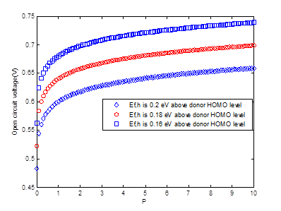
Figure 1.  , in equation (10) plotted as a function of electron: hole mobility ratio,
  .
.
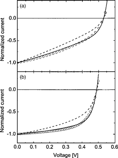
Figure 2. Measured current-voltage characteristics normalized to the short-circuit current (open circles) of two P3HT/PCBM solar cells annealed at 52°C (a) and 70°C (b). The solid lines denote simulations using slowest carrier recombination constant , while the dashed lines correspond to simulations using average carrier recombination constant
 .
.  is the dielectric constant (Reproduced with permission from (Koster et al. [23]. Copyright 2006, AIP Publishing LLC.
Figure 2 Measured current-voltage characteristics normalized to the short-circuit current (open circles) of two P3HT/PCBM solar cells annealed at 52 °C (a) and 70°C (b). The solid lines denote simulations using slowest carrier recombination constant , while the dashed lines correspond to simulations using average carrier recombination constant
 .
.  is the dielectric constant (Reproduced with permission from [12].
The analytical results of the dependence of  on the charge carrier mobilities derived in equation (10) agree with the experimental observation as well as with the numerical simulation [12]. In Figure 2(a) and (b) we have reproduced the J-V characteristics measured on P3HT:PCBM bulk heterojunction organic solar cells (BHJ OSCs) annealed at two different temperatures, 52°C and 70°C, respectively (Koster et al., 2006). The measured mobility P3HT:PCBM of electrons and holes is found to be
 (m2V-1s-1),
 (m2V-1s-1) at 52°C (Figure:2a) and
  (m2V-1s-1),
  (m2V-1s-1) at 70°C (Figure 2b) [12]. Using these values, we find that the mobility ratio P decreases from 8.3 x 10³ to 1.0 x 10³ when one anneals the sample at 52°C and 70°C. According to equation (10), this means that one should get a higher value of
  at the annealing temperature of 52°C than at 70°C. This result is quite consistent with that shown in Figures 2(a) and (b), where the measured and simulated
  at 52°C is about 0.04 V higher than that at 70°C. Mobility dependent J-V characteristics have also been simulated by assuming
  [5]. The
  is found to be independent of the charge carrier mobility in the range from 1 to 10-6 cm2/Vs. According to equation (10) also, the mobility dependent term vanishes for
  and hence Voc becomes constant which is consistent with this result.
Abbrevations
H: Hybrid
PTB7:(poly[[4,8-bis[(2-ethylhexyl)oxy]benzo[1,2-b:4,5-b']dithiophene-2,6-diyl][3-fluoro-2-(2- ethylhexy)carbonyl]thieno[3,4-b]thiophenediyl]])
PCBM: 1-(3-methoxycarbonyl)-propyl-1-phenyl-(6,6)C
PCDTBT:poly[N-9''-hepta-decanyl-2,7-carbazole-alt-5,5-(4',7'-di-2-thienyl-2',1',3'-benzothiadiazole)]
P3HT: poly(3-hexylthiophene)
MDMOPPV:poly[2-methoxy-5-(3’,7’-dimethyloctyloxy)-1-4-phenylene vinylene]
PBDTBDD:poly(((4,8-Bis(5-(2-ethylhexyl)thiophen-2-yl)benzo[1,2-b:4,5-b′]dithiophene-2,6-diyl) bis(trimethyl))-co-(5,7-bis(2-ethylhexyl)benzo[1,2-c:4,5-c′]dithiophene-4,8-dione))
Bis-PCBM: bisadduct of phenyl-C61-butyric acid methyl ester)
MEHPPV :poly[2-methoxy-5-(2-ethylhexyloxy)-1,4-phenylenevinylene]
Si-PCPDTBT:poly[2,1,3-benzothiadiazole-4,7-diyl[4,4-bis(2-ethylhexyl)-4H-cyclopenta2,1-b:3,4-b′]dithiophene-siloe 2,6-diyl]]
nc-ZnO: Zinc oxide nanoparticles
Si NCs: Silicon nanocrystals
Discussions
According to equation (10) the open-circuit voltage becomes equal to the effective band gap energy and hence independent of the charge carrier mobilities when the hole quasi-Fermi level is equal to the HOMO level of the donor molecule and the electron and hole mobilities are equal. It is to be noted that the  derived in equation (10), depends on the electron and hole mobilities directly. The material with
 will have greater energy loss
 and hence lower
  in comparison with materials with
 , which will have lesser
  and hence higher
  . From this point of view, one may prefer to use materials with
  for obtaining higher
 in OSCs.
As stated above, in the calculation of  from equation (10), we have assumed a constant value for
  eV, which is valid only if the charge carrier concentration remains constant and that means the mobilities of charge carriers are not very high or very low. For example, in OSCs based on P3HT:PCBM where a mobility ratio
 =10 is considered [19], it is found that if both charge carrier mobilities at this ratio are high, then this will lead to the efficient extraction of charge carriers which reduces the charge carrier concentration. This reduction in carrier concentration is expected to draw the hole quasi Fermi level away from the HOMO level of the donor material, which according to equation (10) will reduce the
  . This will eventually reduce the PCE as found in [19]. Likewise, at low charge carrier mobilities at the same ratio, the recombination will be enhanced which will reduce the short circuit current [6, 19], leading to reduction in PCE. In this view, the derived
  in equation (10) may be regarded to be valid only at moderate electron and hole mobilities leading to high PCE.
Table 2 Donor- Acceptor materials, Donor HOMO level  , Acceptor LUMO level
  , Effective band gap
  , transport loss term
  and
and  from equation (10) .
For highlighting the role of the charge carrier mobility, it may be desirable to consider the two DA combination materials MDMOPPV:PCBM and P3HT:Bis-PCBM in Table 2. These two combinations have the same effective gap of 1.30 eV but the second term of  in equation (10) is 0.06 eV for the first combination and zero for the second (Table 2). As a result the value of
  is less in the first combination than that in the second, producing higher
  (0.96 eV) in MDMOPPV:PCBM in comparison with that of 0.89 eV in P3HT:Bis-PCBM. It may be interesting to note that, using
  eV in equation (10), we get,
  which shows that the loss of 0.4 eV due to the energy difference is much bigger than the second term due to the charge transport whose calculated values are listed in column 6 of Table 2.
Donor
material |
 (eV) (eV)
|
Acceptor
material |
 (eV) (eV)
|
 (eV) (eV)
|
 (eV) (eV)
|
 (V) (V) |
 (V) (V)
|
Ref. |
PTB7 |
5.15 |
PCBM |
4.06 |
1.09 |
0.04 |
0.73 |
0.75 |
[20] |
PCDTBT |
5.50 |
PCBM |
4.30 [11] |
1.20 |
0.12 |
0.92 |
0.85 |
[21] |
P3HT |
5.10 |
PCBM |
4.06 |
1.04 |
0.06 |
0.69 |
0.63 |
[26] |
MDMOPPV |
5.36 |
PCBM |
4.06 |
1.30 |
0.06 |
0.96 |
0.83 |
[11] |
PBDTBDD |
5.23 |
Bis-PCBM |
3.80 |
1.43 |
-0.01 |
0.97 |
1.00 |
[10] |
PBDTBDD |
5.23 |
PCBM |
3.94 |
1.29 |
-0.01 |
0.88 |
0.86
|
[10] |
P3HT |
5.10 |
Bis-PCBM |
3.80 |
1.30 |
0.00 |
0.89 |
0.74 |
[10] |
MEHPPV |
5.20 |
PCBM |
3.95 |
1.00 |
0.18 |
0.88 |
0.74 |
[13] |
Si-PCPDTBT |
4.86 |
PCBM |
3.88 |
0.98 |
0.05 |
0.63 |
0.59
|
[22] |
MDMOPPV |
5.20 |
nc-ZnO |
4.20 |
1.00 |
0.04 |
0.64 |
0.74 |
[23]
|
P3HT |
5.10 |
Si-NCs |
3.95 |
1.15 |
0.00 |
0.75 |
0.75 |
[24]
|
2021 Copyright OAT. All rights reserv
Table 2. Donor- Acceptor materials, Donor HOMO level  , Acceptor LUMO level
  , Effective band gap
  , transport loss term
  and
and  from equation (10) .
Conclusion
We have derived a mobility dependant expression for  of OSCs and OHSCs. We have shown that if the difference between the electron and hole mobilities is small, the
  derived here does not depend on the charge carrier mobilities significantly. According to our model, the
  of a DA material depends on two terms; the first depends on the energetics and the second on the electron and hole mobility ratio. This may be expected to be useful in predicting the PCE of OSCs and OHSCs prior to their fabrications from a combination of DA materials.
References
- Rita Narayan M, Singh J (2013) Study of the Mechanism and Rate of Exciton Dissociation at the Donor-Acceptor Interface in Bulk-Heterojunction Organic Solar Cells. Journal of Applied Physics 114: 735101-735107.
- Ompong D, Singh J (2015) Diffusion length and Langevin recombination of singlet and triplet excitons in organic heterojunction solar cells. Chemphyschem 16: 1281-1285. [Crossref]
- Narayan MR, Singh J (2012) Roles of Binding Energy and Diffusion Length of Singlet and Triplet Excitons In Organic Heterojunction Solar Cells. Physica Status Solidi 9: 2386-2389.
- Narayan MR, Singh J (2015) Excitonic and Photonic Processes In Materials, Singapore, Springer.
- Würfel U, Neher D, Spies A, Albrecht S (2015) Impact of charge transport on current-voltage characteristics and power-conversion efficiency of organic solar cells. Nat Commun 6: 6951. [Crossref]
- Deibel C, Wagenpfahl A, Dyakonov V (2008) Influence of Charge Carrier Mobility on the Performance of Organic Solar Cells. Physica Status Solidi (Rrl)- Rapid Research Letters 2: 175-177.
- Gregg BA (2003) Excitonic Solar Cells. The Journal of Physical Chemistry B 107: 4688-4698.
- Brabec CJ, Cravino A, Meissner D, Sariciftci NS, Fromherz T, et al. (2001) Origin of the Open Circuit Voltage of Plastic Solar Cells. Advanced Functional Materials 11: 374-380.
- Scharber MC, Mühlbacher D, Koppe M, Denk P, Waldauf C, et al. (2006) Design Rules For Donors In Bulk-Heterojunction Solar Cells-Towards 10% Energy-Conversion Efficiency. Advanced Materials 18: 789-794.
- Ye L, Zhang S, Qian D, Wang Q, Hou J (2013) Application of Bis-Pcbm In Polymer Solar Cells With Improved Voltage. The Journal of Physical Chemistry C 117: 25360-25366
- Cravino A (2007) Origin of the Open Circuit Voltage Of Donor-Acceptor Solar Cells: Do Polaronic Energy Levels Play A Role? Applied Physics Letters 91: 243502.
- Koster LJA, Van Strien WJ, Beek WJE, Blom PWM (2007) Device Operation Of Conjugated Polymer/Zinc Oxide Bulk Heterojunction Solar Cells. Advanced Functional Materials 17: 1297-1302.
- Dastoor PC, Mcneill CR, Frohne H, Foster CJ, Dean B, et al. (2007) Understanding And Improving Solid-State Polymer/C60-Fullerene Bulk-Heterojunction Solar Cells Using Ternary Porphyrin Blends. The Journal of Physical Chemistry C 111: 15415-15426.
- Liu Y, Zhao J, Li Z, Mu C, Ma W, et al. (2014) Aggregation and morphology control enables multiple cases of high-efficiency polymer solar cells. Scharber [Crossref]
- Proctor CM, Love JA, Nguyen TQ (2014) Mobility guidelines for high fill factor solution-processed small molecule solar cells. Adv Mater 26: 5957-5961. [Crossref]
- Servaites JD, Ratner MA, Marks TJ (2009) Practical Efficiency Limits In Organic Photovoltaic Cells: Functional Dependence of Fill Factor And External Quantum Efficiency. Applied Physics Letters 95: 163302.
- Nelson J (2003) The Physics of Solar Cells, London, Imperial College Press
- Wagenpfahl A, Rauh D, Binder M, Deibel C, Dyakonov V (2010) S-Shaped Current-Voltage Characteristics Of Organic Solar Devices. Physical Review B 82: 115306.
- Mandoc MM, Koster LJA, Blom PWM (2007) Optimum Charge Carrier Mobility in Organic Solar Cells. Applied Physics Letters 90: 133504.
- Ebenhoch B, Thomson SAJ, Genevicius K, Juška G, Samuel IDW (2015) Charge Carrier Mobility of the Organic Photovoltaic Materials Ptb7 And Pc71bm And Its Influence On Device Performance. Organic Electronics 22: 62-68.
- Philippa B, Stolterfoht M, Burn PL, Juška G, Meredith P, et al. (2014) The impact of hot charge carrier mobility on photocurrent losses in polymer-based solar cells. Sci Rep 4: 5695. [Crossref]
- Albrecht S, Vandewal K, Tumbleston JR, Fischer FS, Douglas JD, et al. (2014) On the efficiency of charge transfer state splitting in polymer: fullerene solar cells. Adv Mater 26: 2533-2539. [Crossref]
- Koster LJA, Mihailetchi VD, Blom PWM (2006) Bimolecular Recombination in Polymer/Fullerene Bulk Heterojunction Solar Cells. Applied Physics Letters 88: 052104.
- Liu CY, Holman ZC, Kortshagen UR (2009) Hybrid solar cells from P3HT and silicon nanocrystals. Nano Lett 9: 449-452. [Crossref]
- Liu XD, Xu Z, Zhang FJ, Zhao SL, Zhang TH, et al. (2010) Influence of Small-Molecule Material on Performance of Polymer Solar Cells Based On Meh-Ppv:Pcbm Blend. Chinese Physics B 19: 118601.
- Sun Y, Takacs CJ, Cowan SR, Seo JH, Gong X, et al. (2011) Efficient, air-stable bulk heterojunction polymer solar cells using MoO(x) as the anode interfacial layer. Adv Mater 23: 2226-2230. [Crossref]