Abstract
Background
Detailed features of electrocardiogram (ECG) are inspected manually in short segments. With the increasing need to collect longer ECG signals, beat-by-beat inspection of ECG signals becomes a challenging task. A new method that allows simultaneous analysis of micro- and macro-features of ECG signals is needed.
Methods and results
Using signal processing tools, ECG is transformed into the electrocardiomatrix (ECM), which displays more than two adjacent P-QRS-T complexes on the Y-axis, consecutively numbered heart cycles on the X-axis, and voltage values on the Z-axis as a heat map. The resulting ECM permits both compact display of short- and long-range ECG rhythms, and a beat-by-beat survey of all ECG morphological features. We applied ECM analysis to ECG data from patients with cardiac arrhythmias and discovered subtle and abnormal ECG features, some of which were not reported using traditional manual scoring.
Conclusions
These data demonstrate that ECM permits potentially more accurate and comprehensive diagnosis of heart abnormalities, and may facilitate basic and noninvasive research of the heart.
Key words
arrhythmia, diagnosis, electrocardiogram
Introduction
ECG is one of the most widely used tools for noninvasive diagnosis of cardiovascular diseases and for basic research of the heart. It is used to measure the chronology and morphology of heartbeats, clinically useful in monitoring cardiovascular pathology and pharmacology. Traditionally, detailed ECG morphology is analyzed manually in segments of a few seconds, while ECG rhythm analysis is performed on long segments that are difficult to analyze in detail. As such, simultaneous analysis of detailed ECG morphology and cardiac rhythm has presented a practical challenge.
In addition, while a short ECG recording is routinely and quickly performed in clinics, long ECG recording has become a common method to identify cardiac abnormalities that occur sporadically in many patients. Continuous recording for hours and days by portable Holter or event monitors [1,2] generates ECG data spanning over 100, 000 heartbeats over the course of a day. Manually sifting through such long ECG data beat-by-beat is a time-consuming, error-prone, and frequently impossible task. Holter data is therefore analyzed largely by trained specialists using proprietary algorithms. Data summarized and provided to physicians consist of a large set of numbers including, but not limited to, heart rate, RR intervals, and quality and quantity of arrhythmias observed. To make sense of these data, it is frequently necessary to visit the raw ECG data beat-by-beat for feature examination. With increasing demands for even longer ECG monitoring [3,4], a new approach is needed to allow one-glance survey and easier visual inspection of the entire ECG record and rapid extraction of all disease-relevant features from a large set of ECG data.
Here, we demonstrate a new technique, electrocardiomatrix (ECM), to comprehensively analyze ECG signals utilizing modern signal processing methods.
Methods
Raw ECG data was first processed to remove baseline drift using second-order Butterworth high-pass filtering with a cutoff frequency at 1 Hz (‘butter.m’ and ‘filtfilt.m’ in MATLAB signal toolbox, MathWorks Inc., Natick, MA). R-peaks were then automatically detected using a modified variable threshold method [5]. Specifically, an amplitude threshold (97% in this study) within each non-overlapping 10-second epoch was applied to select the candidates for R-peaks. An additional requirement was applied to ensure that the selected R peaks maintain a minimum time interval with the adjacent R peaks. In the current study, the interval threshold was selected as 50% of the averaged RR interval values in the preceding 10-second epoch. The automatically detected R-peaks were subsequently validated through a custom graphical user interface created in MATLAB (MathWorks Inc., Natick, MA).
Results
To demonstrate the ECM method and to assess its performance, we applied it to the analysis of human ECG signals from the annotated MIT-BIH arrhythmia database (http://www.physionet.org/physiobank/database/mitdb/) [6,7]. The results from ECM and the annotations from the database were compared. A side-by-side comparison between ECM and selected traditional ECG strips was also provided.
Construction of ECM from ECG data is illustrated conceptually in Figure 1 (patient 123, lead MLII). For a given strip of preprocessed ECG signals (e.g. 7 beats in panel A), each R peak is consecutively numbered (1 to 7 in this example). The signal is then divided into a series of short segments of identical length (2.5 seconds) encompassing two adjacent QRS complexes. Each segment begins 0.5 second before and ends 2 seconds after the 1st of the numbered R peaks. These segments are then sequentially aligned on the center R peaks, which are defined as time 0 on the X-axis (panel B). All segments are then converted into a heat map with color corresponding to voltage (panel C): red indicating more positive voltage and blue indicating more negative voltage. Thus, the time intervals between the R peaks lined at the center and the first R peaks appearing to the right denote RR intervals. The P waves associated with the center R peaks appear as a thin blue line to the left of the center R peak, whereas the T waves appear as a thicker pale blue line to the right of the center R peak line (panel C). The U waves [8] are detectable in this patient and appear as a thinner faint blue line to the right side of the T waves. The resulting matrix is rotated 90 degrees such that the numbered R peaks (or time elapsed from the start of the recorded signal) appear on the X-axis and time (seconds or milliseconds) from the center R peaks is shown on the Y-axis (panel D). Thus, each heartbeat is vertically displayed with its P wave represented below the center R peak, the T wave above the center R peak, and U wave (if present) above the T wave. ECG intervals (RR, PR, QRS, ST, and QT) are visually apparent and are easily identifiable. The aligned center QRS complexes marked by a red vertical line in panel D are further expanded in panel E and compared with the first of the 6 heartbeats in ECG format (rotated 90° counter-clock wise). In this expanded view, the negative S wave is seen as a deep blue line above the R peak (panel E).
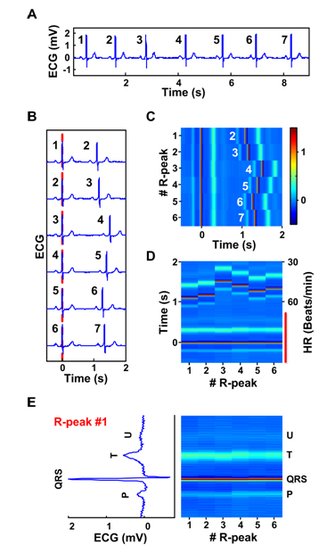
Figure 1. Construction of the ECM. A: A ECG strip with 7 beats numbered consecutively (patient 123, lead MLII). B: The ECG signal in panel A is segmented into a series of short segments. C: The segmented and sorted signals are transformed into a heat map. The center R-peaks are aligned at time 0 sec, whereas the adjacent R-peaks are numbered in white letters next to their P-waves. The amplitude of the peaks is indicated by the color bar (-0.5 to 1.5 mV). D: An alternative view of the ECM data in panel C, with heart rate (HR, beats/min) indicated to the right of the matrix and time difference between the center R-peaks and various peaks is indicated to the left side of the panel. E. Lower half of the panel D marked by a red vertical line is expanded to allow side-by-side comparison of ECG features and ECM features. Only the 1st heartbeat, R-peak #1, is shown on the left side after rotating it 90o to the left. The ECM representation of all 6 heartbeats is shown as the colored matrix (right panel). Positions of all peaks in the cardiac signal are indicated on the right side of the ECM.
In the example shown in Figure 1, the segment length was set at 2.5 seconds. This length can be adjusted to meet the needs of individual ECG analysis so long as it includes, at minimum, the P waves preceding the center R peaks and the adjacent R peaks, so that RR intervals can be obtained for the entire signal. In addition, the colorbar parameter was selected in panel C to reveal maximum information in an ECG signal. This parameter can be chosen according to the needs of individual signal. Normally the same colorbar parameter is selected for the same cardiac signal. In cases where amplitude of the peaks drop or rise suddenly within a signal, one may choose to use varying scales according to the needs of the data.
Two common types of arrhythmias were i2021 Copyright OAT. All rights reserve its potential utility (Figure 2). Panel A (patient 118, lead MLII) compares premature atrial contractions depicted in ECM (lower panel) with standard ECG (upper tracing). Shorter RR intervals (vertically aligned) of premature beats (11th and 16th center R peaks) are each followed by longer RR intervals with no change in the appearance of the premature R peaks. A clear disruption of regularity is seen in the ECM that corresponds to these premature atrial contractions. Panel B (patient 124, lead MLII) shows how premature ventricular contractions are visualized on ECM. The wide QRS complex of a premature ventricular contractions beat is easily identifiable as a complex by elongated width, altered colors (denoting amplitude changes), and altered intervals between consecutive beats. ECM method was successfully applied to capturing all classes of arrhythmias noted in the MIT-BIH arrhythmia database without exception (more than 20 types). These data demonstrate that changes in ECG peak morphology, amplitude, and intervals between various peaks can be simultaneously and visually detected using ECM method.
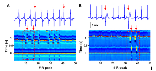
Figure 2. Premature heartbeats in ECM format. A: Premature atrial contraction (patient 118, lead MLII) shown in conventional ECG (top) and ECM format (bottom). Red arrows mark the premature atrial beats. The boxed area within the ECM shows the regions depicted in the standard ECG strip above. B: Premature ventricular contraction (patient 124, lead MLII) shown in conventional ECG format (top) and in ECM format (bottom). Red arrows mark the premature ventricular beats. The amplitude of the peaks is indicated by the color bar (-0.5 to 1.5 mV) shown in Figure 1C.
To further validate this tool for analysis of subtle ECG features, several morphological ECG alterations that do not involve RR interval changes and that are not easily identified by current algorithms were analyzed using the ECM method (Figure 3). ST depression in patient 112 (lead MLII) is demonstrated by a change in color depicting ST segment-specific lower voltage (deeper blue than the PR segment for this patient). The presence of ST depression was noted for this patient in standard scoring of the recording. Chronic ST elevation, on the other hand, is shown in patient 115 (lead MLII), with ST segments elevated when compared with the PR segments. In the original analysis of this patient, this feature was not reported.
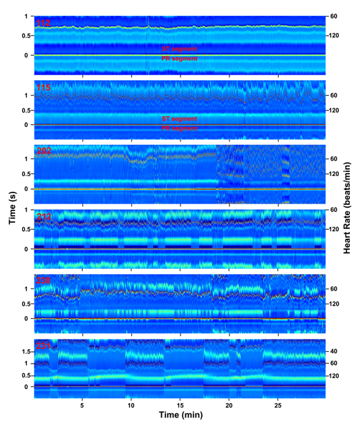
Figure 3. Abnormal ECG features (RR interval independent) visualized in ECM format. ECG signals from patients 112, 115, 202, 212, 230, and 231 (top to bottom; all from lead MLII) are transformed into ECM panels and displayed as function of time (minutes) in X-axis, RR intervals (seconds; left label) and heart rate (beats/minute; right label) in Y-axis. The amplitude of the peaks is indicated in the Z-axis by the color bar (-0.5 to 1.5 mV) shown in Figure 1C. ST- and PR-segments are indicated for ECG signals #112 and #115.
ECM analysis of atrial fibrillation in patient 202 (lead MLII) shows highly disordered signals (18:00 – 30:00). In the annotations provided by physicians on this record, the signals between 18:45 and 30:00 are all classified as atrial fibrillation, except the segment between 25:58 and 27:55, which is annotated as atrial flutter with 2:1 conduction. Our ECM analysis shows that the signals between 20:00 and 21:26 are in fact dominated more by atrial flutter with 2:1 conduction than by atrial fibrillation. Other features evident in ECM but absent in the annotated record include sudden expansion of PR interval beginning at 10:00 and broadening of the P-wave width, both of which lasted until the onset of atrial fibrillation. Both features coincided with the sudden increase in heart rate at 8th minute, however, persisted even after heart rate recovered to lower baseline values (13:00 – 18:00).
For patient 212 (lead MLII) with intermittent right bundle branch block (RBBB) signals, ECM analysis clearly displays long-term intrusion of this abnormality represented by deep blue S waves that appear periodically. The appearance of RBBB beats is tightly associated with two additional features: (1) altered morphology of T waves with wider and more elevated appearance and (2) reduced amplitude of R waves by 0.48 mV. In addition, while the original record indicated noisy signals at 18:42 and 26:45, they made no impact on the ECM-based signal analysis.
For patient 230 (lead MLII) with Wolff-Parkinson-White (WPW) syndrome, intermittent shortening of the PR interval and wider QRS morphology are apparent. The WPW beats are clearly associated with narrower T waves with much lower amplitude. Moreover, it is evident on the ECM that the WPW beats are tightly linked with elevated R peak amplitude.
Second-degree atrioventricular block is apparent for patient 231 (lead MLII) with two P waves for every one QRS complex (2:1 Mobitz II block) in portion of the signals. ECM analysis also shows intermittent RBBB tightly associated with the normal sinus beats and only occasionally appearing in atrioventricular blocked beats. A notable feature not described by standard analysis is the expansion of QT intervals specifically and invariably associated with the atrioventricular block.
Discussion
This paper introduced ECM, a new technique to allow efficient and comprehensive analysis of ECG data to facilitate disease diagnosis. ECM analysis offers the following advantages: 1) compact, comprehensive visual representation of long ECG signals; 2) display of all ECG intervals including RR, PR, QRS, ST, and QT intervals; 3) color-coded tracking of ECG amplitude changes including ST-depression/-elevation and left/right bundle branch block; 4) visualization of ECG morphology changes including P waves, QRS complex, T waves; and 5) real-time tracing of heart rate variations (inverse function of RR intervals). Most importantly, these features are all displayed in one compact matrix format that can be intuitively analyzed; colorful representation of each peak allows easy and intuitive identification of amplitude changes of ECG peaks; arrhythmic beats can be studied in their endogenous context; and key findings can be correlated easily with time-stamped events noted by patients.
To document the utility of our method, we transformed several patients’ ECG data into ECM format and compared the results with the conventional ECG interpretations. In each case, we captured all reported abnormalities of the patients’ ECG on ECM. In several cases, we were able to identify additional features associated with the cardiac abnormalities of the patients that were not described using standard analysis. These data demonstrate the usefulness of ECM analysis in cardiac studies and in diagnosis of clinically-relevant cardiac pathology. Given the universal importance of the ECG, we expect that this new method will have clinical, research, and educational uses [9].
J.B. and M.M.W. conceived the project; D.L. and G.X. wrote analysis programs; S.R. and F.T. analyzed the data; F.T. and J.B. wrote the paper.
Acknowledgement
The authors thank Louis D’Alecy, Drew Bennett, Hamid Ghanbari, Jose Jalife, Richard Mortensen, Mohammed Saeed, and Kevin Ward for valuable input and suggestions over the course of this project and C. Patrick Crook, Jon Dean, Talha Ghazi, and Sean Huff for comments on the manuscript.
Funding information
This work was supported by the Department of Molecular and Integrative Physiology and the Summer Undergraduate Research in Physiology fellowship (to S.R.) funded by the NHLBI (R25HL108842; to J.B.).
Competing interest
The electrocardiomatrix (ECM) technology is pending for patent protection.
References
- Ritter P (2013) Holter in monitoring of cardiac pacing. Prog Cardiovasc Dis 56: 211-223. [Crossref]
- Rosero SZ, Kutyifa V, Olshansky B, Zareba W (2013) Ambulatory ECG monitoring in atrial fibrillation management. Prog Cardiovasc Dis 56: 143-152. [Crossref]
- Gladstone DJ, Spring M, Dorian P, Panzov V, Thorpe KE, et al. (2014) Atrial fibrillation in patients with cryptogenic stroke. N Engl J Med 370: 2467-2477. [Crossref]
- Sanna T, Diener HC, Passman RS, Di Lazzaro V, Bernstein RA, et al. (2014) Cryptogenic stroke and underlying atrial fibrillation. N Engl J Med 370: 2478-2486. [Crossref]
- Kew HP, Jeong DU (2011) Variable threshold method for ECG R-peak detection. J Med Syst 35: 1085-1094. [Crossref]
- Goldberger AL, Amaral LA, Glass L, Hausdorff JM, Ivanov PC, et al. (2000) Physiobank, physiotoolkit, and physionet: Components of a new research resource for complex physiologic signals. Circulation 101: e215-e220. [Crossref]
- Moody GB, Mark RG (2001) The impact of the MIT-BIH arrhythmia database. IEEE Eng Med Biol Mag 20: 45-50. [Crossref]
- Pérez Riera AR, Ferreira C, Filho CF, Ferreira M, Meneghini A, et al. (2008) The enigmatic sixth wave of the electrocardiogram: the U wave. Cardiol J 15: 408-421. [Crossref]
- Yong CM, Froelicher V, Wagner G (2013) The electrocardiogram at a crossroads. Circulation 128: 79-82. [Crossref]