Abstract
An 60 year-old obese class I woman (weight 80 kg, height 160 cm, body mass index 31.25) was mechanically ventilated for an abdominal surgery, using Fabius GS anesthesia machine (Draeger Medical, AG &Co, Lubeck, Germany). Before usage, the anesthesia machine had undergone a standard morning operational check up in which all apparatus components passed. A set tidal volume (TV) of 600 ml was installed. Although the expected TV administered to the patient was supposed to be within the range of the predetermined values (600 ml), the actual TV that had been measured by the Spirolog flow sensor fluctuated between 270 to 290 ml only. Physical examination including inspection of gross chest movement and lung auscultation revealed a fairly ventilated patient. End tidal CO2 was around 35 mmHg, peak inspiratory pressure 23-35mmHg and the state of muscle relaxation adequate. Raising the fresh gas flow to 6 liters per minute, switching to manual ventilation mode and compressing the inflated breathing bag with semi-closed adjustable pressure limiting valve to check for leaks did not unveil the reason for a leak neither within the anesthesia machine nor in the breathing circuit and airways surroundings. To rule out an unnoticed miniature puncture in the disposable circle tubing, it was replaced by a new kit and a second leak test was made, which again passed without revealing the source to any faulty element.
In depth systematic investigation revealed that the malfunction occurred from a damaged Spirolog flow sensor causing inaccuracy of TV measurement due to a technical problem which had not yet been described.
The Spirolog serves as a flow sensors for several models of Draeger ventilators (the Evita Series and Savina) and anesthesia machines (Apollo, Primus, Fabius GS and Tiro, Julian, Cato, Cicero and Sulla). The physical principle for its action is based on thermal anemometry. Anemometer, a term derived from the Greek word anemos, meaning wind, is an instrument for measuring flow velocity, commonly used in meteorology to determine wind speed.
Thermal anemometry is the most common method to measure flowing gas velocity. This is done by determining the convective heat loss from an electrically resistive heated (hot) wire element, placed in the gas pathway, to its surrounding gaseous phase in motion. If the heated element parameters and gas properties are kept fixed, then gas velocity is the only variable and the heat loss can be interpreted as gas flow rate [1,2].
Hot-wire anemometer uses a small probe constructed from short length, circular wire, usually made of platinum. It operates at very high temperatures [3], and is incorporated into a balanced Wheatstone bridge circuit. Heat loss and cooling of the wire changes its resistance and unbalances the bridge. A feedback mechanism compensates for the cooling effect of the gas by correcting current is applied to the wire to maintain a constant temperature and thus restores the balance in the Wheatstone bridge. This current is inferred in terms of gas velocity or flow.
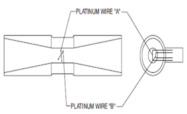
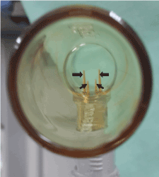
The Spirolog flow sensor apparatus (Figures 1-3) comprises a hot-wire assembly [4], positioned within the expiratory limb of the breathing circuit and constructed of two sets of a micrometric thin platinum wire filament (that can be visualized in Figure 4a, black arrow), each of which is mounted and stretched between two parallel adjacent needle-shaped conducting pins (Figure 2, thick and thin black arrows), through which an electric current is applied to heat the wire to a temperature above the ambient. The first wire (Figure 1, platinum wire "A") is the one that cools as gas flows past it. Gas velocity is calculated by way of flow and displayed as TV on the anesthesia machine monitor screen. The second wire (Figure 1, platinum wire "B") compensates for interferences from different gases present in the fresh gas delivered to the patient. Each gas has specific thermal conductivity, thus the amount of heat removed from the wire is indicative for gas composition.

Figure 1. Schematic drawing of Spirolog anemometer.

Figure 2. A view inside the plastic tube housing (which is shown in 3, white arrowheads) of a brand new Spirolog flow sensor. Two pairs of needle-shaped conducting pins (thick and thin black arrow) positioned parallel to each other, restraining a micrometric thin platinum wire filament (that can be visualized in figure 4a, black arrow) mounted between their tops, anchored and stretched between.

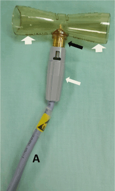
Figure 3. The Spirolog flow sensor. The hot-wire assembly (black arrow) built at one end into a plastic tube housing (white arrowheads) and at its opposite end attached to an adapter (white arrow) connected to a cable (A).

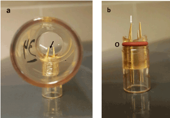
Figure 4. a. A view inside the plastic tube housing of the faulty Spirolog flow sensor. The left needle-shaped pins are bent and distorted (white arrow). The black arrow points at the micrometric thin platinum wire filament mounted between the tops of the needle-shaped pins, although in the image it is hanged loose instead its original stretched state. b. The hot wire assembly detached from its plastic tube housing showing the bent needle-shaped pin (white arrow) and the O-ring (O).
Practically, the Spirolog flow sensor (Figure 3) is built of a plastic tube housing, made of two inverted cones connected to each other (Figure 3, white arrowheads) that acts as both, a hot-wire assembly holder and a fresh gas conduit, and to which the hot-wire assembly (Figure 4b) is embedded into and tightly affixed by the aid on an O-ring (Figure 4b, O). At its opposite end, the hot-wire assembly is attached to an adapter (Figure 3, white arrow) which is in turn connected to a transmission cable (Figure3, A) that is plugged to a control console at the inner side of the anesthesia machine.
The exact distance between the tops of each pair of needle-shaped pins, positioned parallel to each other and restrain the wire, is essential for creating a predetermined stretch allowing it to stay aligned in a straight line. Such tension is critical to reliably measure temperature changes from gas flow through the wire. It is therefore obvious that any alteration in the parallelism of the two needle-shaped pins will result in erroneous flow velocity readings.
In this case, one of the needle-shaped pins of the Spirolog flow sensor became bent and distorted (Figure 4a and 4b, white arrows). The exact reason for such bending is unknown. We propose a theoretical hypothesis, which is not entirely unreasonable, regarding the sequence of the events that led to thermal function of the Spirolog flow sensor described in this case, where by the cable which connects the hot-wire assembly was accidently but forcefully pulled, tearing the assembly off the plastic tube housing. The anesthesiologist in charge of the event who realized the damage tried to affix it but reattached the hot wire assembly into the plastic tube housing incorrectly, in doing so he pressed on one needle-shaped pins, causing it to incline inward, loosening the original stretched state of the hot-wire filament. As a result, the wire lost its thermal properties and thus the ability to measure the true flow velocity according to a constant temperature principle.
A question still remains why the anesthesia machine, having a built-in checkup mechanism for the flow sensor apparatus, did not diagnosed the described problem. It is known that the Spirolog flow sensor is periodically calibrated automatically at the start-up of the anesthesia machine or manually if the operator suspects flow monitoring inaccuracy. During this process, all control valves are closed, fresh gas flow of any kind is interrupted and the wire filament is heated to temperatures as high as 800°C. This is termed "zero calibration procedure". However, such calibration process is performed only at a zero point with no gas flow onto the hot-wire assembly. There is no additional calibration step with a gas flowing in a given rate, a so-called two-point calibration procedure. If existed, it theoretically could have revealed the faulty flow sensor apparatus. Nonetheless this is not the case herein. Fortunately, because the described problem is so rare, in our opinion there is no need to complicate the calibration procedure and add a second calibration point, besides the existing one.
In general, mechanical problems with Spirolog flow sensor are very uncommon and it has been proven over the years of operation as unfailing and accurate [5]. Only few incidents of device malfunction were reported. In one, alcohol or other flammable solutions used for periodic disinfection remained within the hot-wire assembly and ignited during sensor calibration [6]. In another, a small amount of material had adhered to the hot-wire filaments, burned during calibration, produced smoke and damaged the sensor and other components within the breathing system [7]. Likewise, a case of thin transparent film between the platinum wires, which altered the calibration characteristics of the Spirolog and led to alarm activation had been reported [8]. Yet more dangerous combustive event occurred in the expiratory valve of a Cato anesthesia machine which uses the Spirolog flow sensor. The high temperatures of the hot-wire assembly had been incriminated to cause ignition of Xylocaine pump spray containing high concentration of flammable ethanol, which was used to lubricate the internal surface of endotracheal tube lumen to enable easier suctioning of viscous secretions, and given together with 100% oxygenation few minutes before extubation [3].
Common to all the fore mentioned reports is the intrusion of a foreign material into the breathing circuit, where it was not supposed to be. This led not only to erroneous reading of flow meter but also to an impending life-threatening problem during mechanical ventilation. That is not the cause of malfunctioned flow sensor in the present case where supposedly improvised repair of technical failure by an unauthorized person caused inaccurate ventilation parameters and potential risk to the patient.
2021 Copyright OAT. All rights reserv
Besides thermal anemometry, there are other methods to determine gas velocity in the breathing circuit of the anesthesia machine [9]. Several models the Datex-Ohmeda series use pneumotachograph in which a resistance, built from small-bore tubes arranged in parallel, is put in the gas pathway so that the gas flow must pass through, resulting in pressure drop across it. The pressure difference before and after the resistance is directly proportional to the gas flow rate. Sometimes condensation can build-up and block the resistance tubes and might compromise the sensor accuracy. Another method, mechanical flow transducer, is used in the Siemens Servo series of intensive care ventilators. The gas flow is split into a small side channel in which a thin metal disc supported on a flexible pin is placed at right angles to the direction of gas flow. The disc backward displacement is measured by a strain gauge that produces an electrical signal which is processed to display gas velocity. The ultrasonic flow meter is based on change in velocity of an ultrasound signal corresponding the change in gas flow according to the Doppler principle. A pair of ultrasound beams directed in opposite direction is situated in the gas pathway. As gas flows, the time difference between the two beams correlates with gas velocity and flow rate. However, for both, the mechanical flow transducer as well as the ultrasonic flow meter, the calculated flow rate may be influenced by gas composition. Despite some minor inaccuracies and technical problems, all methods to quantify gas velocity in the breathing circuit of the anesthesia machine are clinically reliable and generally safe as shown by many years of field experience.
It is recommended that every mechanical failure in Spirolog flow sensor should be checked and replaced by a qualified technician and not by anyone who is not trained to do so. Nevertheless, it is the obligation of the anesthesiologist and the technical staff to adhere strictly to the manufacturer recommendations which require replacement of the flow sensor every 6 months and its calibration every18 hours [3] to ensure proper and accurate functioning of the anesthesia machine.
References
- Chen J, Fan Z, Zou J, Engel J, Liu C (2003) Two-dimensional micromachined flow sensor array for fluid mechanics studies. J Aerospace Eng 16: 85-97.
- Miller IS, Shah DA, Antonia RA (1987) A constant temperature hot-wire anemometer. J Phys E Sci Instrum 20: 311-314.
- Aso Kanno T, Aso C, Saito S, Yoshikawa D, Goto F (2003) A combustive destruction of expiration valve in an anesthetic circuit. Anesthesiology 98: 577-579. [Crossref]
- (2003) Draeger Medical Inc. Fabius GS Technical Service Manual. Part number 4117104, pp: 2-41.
- Chakrabarti MK, Loh L (1984) Evaluation of Spirolog I volume meter. Anaesthesia 39: 268-271. [Crossref]
- [No authors listed] (2013) ECRI Institute provides additional recommendations to reduce risk of igniting foreign material in Draeger anesthesia unit flow sensors. Health Devices 42: 201. [Crossref]
- ECRI Institute (2009) Hazard report. Flammable material introduced into Draeger ventilator and anesthesia unit flow sensors could ignite, posing risks to patients. Health devices 38: 339-340. [Crossref]
- Vinay B, Sriganesh K (2013) Importance of education in interpretation of alarms. Anesth Analg 116: 735-736. [Crossref]
- Garg R, Gupta RC (2013) Analysis of oxygen, anaesthesia agent and flows in anaesthesia machine. Indian J Anaesth 57: 481-488. [Crossref]


