Abstract
The rehabilitation of facial defects is a complex task requiring a specific design of the technique to be used in individual patient. The disfigurement associated with the loss of an eye can cause significant physical and emotional problems. Various treatment modalities are available. This case report details the clinical management of a patient following enbloc removal of an eye. Fabrication of a two piece sectional magnet retained orbital prosthesis has been detailed.
Key words
magnets, orbital prosthesis, two piece
Introduction
The loss of an eye can be a very traumatic event in a person’s life, not only medically, but also emotionally. For many, the face and eyes help represent who they are, and it is common for these patients to feel that a part of them has been lost. Taylor has expressed that ‘The psychology of an individual is a cumulative reflection of his past and present experiences’ [1]. Any facial deformity is a severe debilitating factor for the psychology of an individual. Surgical removal of an eye is especially a severe handicap to a patient because the most important sensory organ of communication is lost. Thus, the loss of an eye is a severe handicap for a patient both physically as well as emotionally and it is our responsibility as Prosthodontics to emotionally be supportive to the patients during the various phases of treatment which they undergo. It is also our responsibility to provide the best possible esthetic result to the patient with the help of an ocular/orbital prosthesis, as required according to the extent of the defect [2].
The loss or absence of an eye may result from a congenital defect, irreparable trauma, a painful blind eye, sympathetic ophthalmia, or the need for histologic confirmation of a suspected diagnosis [3]. Surgical procedures adopted for the removal of an eye are classified by Peyman, Saunders and Goldberg (1987) into three general categories: enucleation, evisceration and exenteration. According to Scoll (1982) enucleation is a surgical procedure in which the globe and the attached portion of the optic nerve are excised from the orbit. Evisceration is removal of the contents of globe while leaving the sclera and extra ocular muscles intact. Exenteration is the most radical of the three procedures and involves removal of the eye, adnexa, and the part of the bony orbit.1 It is indeed impossible to reconstruct an exenterated orbit with autogenous material in an anatomic situation in which there is a total loss of the upper and lower eyelids along with the eye [2].
Orbital prosthesis presents an attractive and viable alternative when esthetic and functional demands are beyond the capacity of local reconstructive efforts. Prosthesis for orbital defects can be made from a variety of materials such as poly-methyl methacrylate, polyurethane elastomer, silicone elastomer, or urethane backed medical grade silicone [2]. Ablative surgical procedure incurs major financial burden, and hence the patient may seek a prosthetic treatment that is economical. Therefore, selection of a reasonable maxillofacial prosthetic material and economically feasible retentive aid should be the goal of rehabilitating such patients.
This article describes the rehabilitation of an orbital defect using a two piece silicone and acrylic prosthesis, wherein retention has been achieved by a combination of anatomic undercuts and magnets.
Case report
A female patient aged 45 years, reported to the Department of Prosthodontics, Government Dental College & Research Institute, Bangalore for the replacement of her exenterated left eye. Patient’s left eye was surgically removed enbloc because of fungal infection (mucormycosis).
Extraoral examination revealed a large orbital defect on the left side with a mild upper undercut and a severe lower undercut (Figure 1). Since the retentive lower undercut cannot be engaged with the help of single piece prosthesis, so a treatment plan was formulated which are consisted of fabrication of a two piece sectional orbital prosthesis consisting of a lower acrylic portion with an outer portion of silicone.
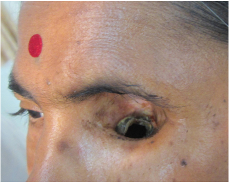
Figure 1. Proximal view of the patient with the orbital defect.
Method
Recording the facial impression and fabrication of facial moulage
The patient was draped for impression procedures and her eyebrows and eyelashes were lubricated with petroleum jelly in order to facilitate removal of the impression material and minimize discomfort to the patient.
After covering an opening in the lower undercut by surgical gauze and a thread (Figure 2), two layers of modelling wax were adapted on the patients face as a spacer over which impression compound was adapted to act as a tray (Figure 3). Holes were made in the impression compound tray, spacer was removed and an impression was made with irreversible hydrocolloid and poured with Type III dental stone (Figure 4).
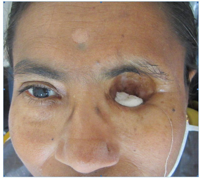
Figure 2. Lower undercut blocked by surgical gauze.
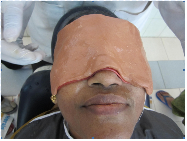
Figure 3. Impression compound adapted to act as a tray.
Lines were marked on the patient’s face with an indelible pencil for symmetrical placement of the orbital prosthesis. A special tray was fabricated for recording the orbital defect with putty consistency polyvinyl siloxane impression material (Aquasil Putty; Dentsply Caulk, Milford, DE, USA). A pickup impression was then made with alginate and poured with type III dental stone to obtain a facial moulage (Figure 5).
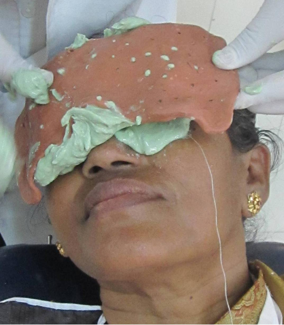
Figure 4. Impression made with irreversible hydrocolloid.
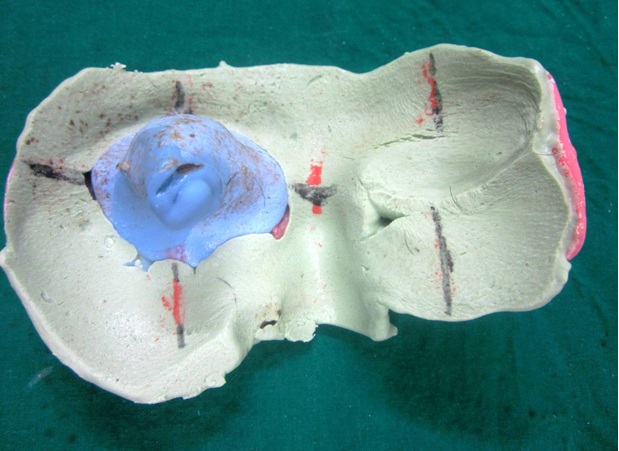
Figure 5. Pickup impression made with alginate.
Acrylic stent fabrication
Clear acrylic stent was fabricated with auto polymerizing acrylic resin (Trevalon clear; Dentsply, New York, PA, USA) engaging the lower undercut (Figure 6).
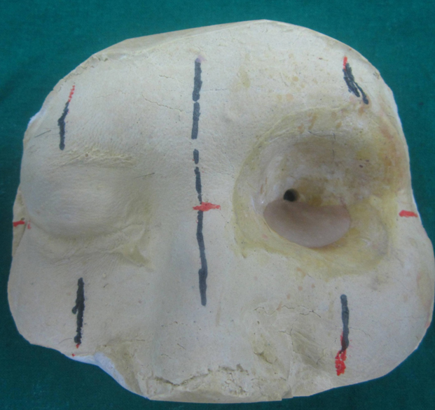
Figure 6. Clear acrylic stent engaging the lower undercut.
Selection of stock acrylic eye shell
A commercially available stock acrylic eye shell matching the sclera and iris colour of the patient’s right eye was selected from an array of stock acrylic eye shells. Accurate alignment of the artificial eye which is inconspicuous to the onlooker is one of the major prerequisites for the aesthetic success of an orbital prosthesis [4,5]. For correct orientation of the eye shell in the defect area, many methods are reported in the literature [6]. Facial measurements were used to orient the shell in this case (Figure 7). The right eye of the patient was maintained in the conversational gaze. A series of vertical lines were marked on the patient’s face; line (A) through the midline of the face and line (B) through the pupil of the right eye. The distance between lines (A) and (B) was measured and a vertical line (B’) was drawn on the defect side from the midline (A). A horizontal line was drawn passing through the pupil of the right eye (C) and extended through the defect on to the left side of face (C’). The horizontal line (C–C’) helped in orienting the shell in correct vertical plane and the vertical lines (B–B’) helped in orienting the shell mediolaterally in the defect when the patient presented a normal straight gaze. These facial measurements were transferred to the cast to assist in wax pattern fabrication.
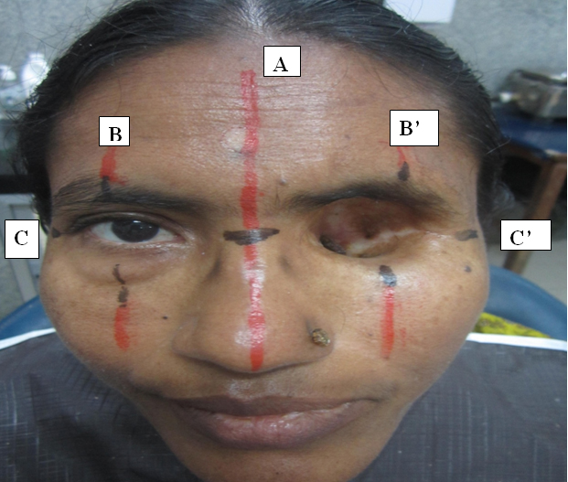
Figure 7. Facial measurements used to orient the eye shell in the defect
Wax pattern sculpting
Defect on the cast was filled with wax and the eye shell was oriented using the above mentioned reference lines (Figure 8). The next step was reproducing the periorbital tissue contours. Carving the anatomic replica of contiguous soft tissues in an orbital prosthesis is an intricate and protracted procedure7. Using graphics software (Photoshop 7.0; Adobe Systems Inc,), patient’s mirror image was used to sculpt the wax pattern of the orbital prosthesis. The wax pattern thus formed was tried on the patient (Figure 8). Correct mediolateral, antero-posterior, inferosuperior positioning and central axis of the prosthesis were confirmed on the patient’s face.
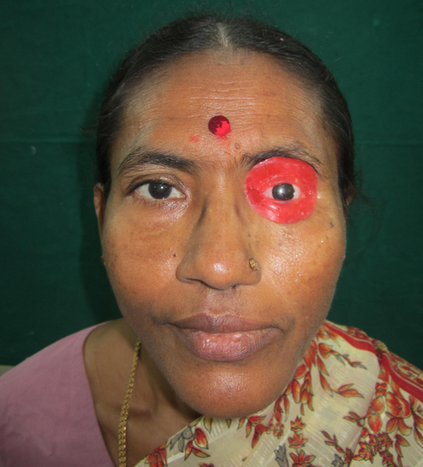
Figure 8. Wax try in of the orbital prosthesis.
A wax pillar was fabricated with magnet (Samarium Cobalt magnet) at one end and the other end protruding into the hole made in upper undercut. The wax pillar was shaped in such a way so as to increase the retention with silicone later. A central groove and lines were marked to orient it in the same relationship with acrylic stent (Figure 9). The wax pillar was converted into a clear acrylic pillar (Figure 10). The next step was to orient the pillar with the acrylic stent. A Magnet was placed over the magnet on the pillar and the whole assembly was positioned in the undercuts on the cast. Position of the magnets was approximately marked on the acrylic stent and resin was hollowed out. It was filled with auto polymerizing resin and the magnet was embedded (Figure 11).
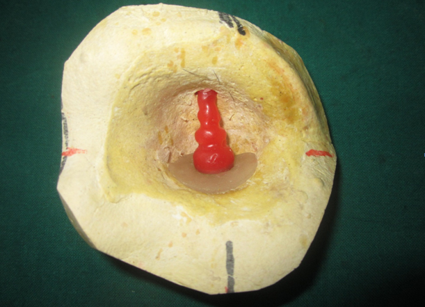
Figure 9. A wax pillar was fabricated with magnet at one end and the other end protruding into the hole made in upper undercut.
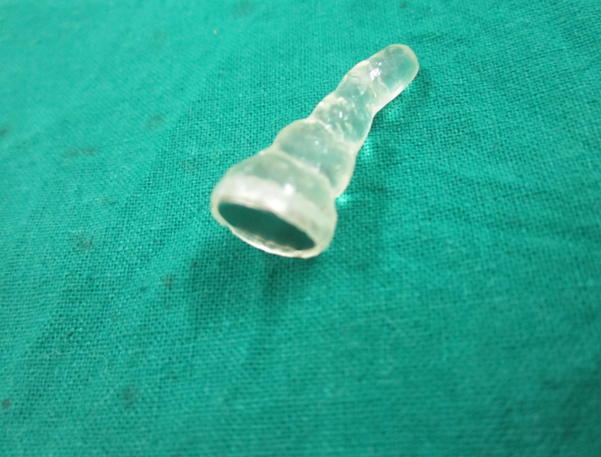
Figure 10. Wax pillar converted into a clear acrylic pillar.
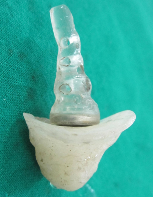
Figure 11. Acrylic stent and pillar.
Stabilization of the eye shell
The difficult task in fabricating an orbital prosthesis is maintaining the position of the eye shell without positional discrepancy during processing. Hence to stabilize the eye shell during processing, a small star shaped auto polymerized acrylic pin was used (Figure 12).
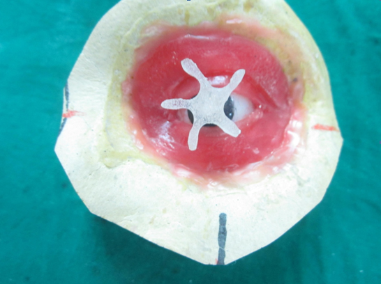
Figure 12. A small star shaped auto polymerized acrylic pin was used to stabilize the eye shell during processing.
Figure 12, A small star shaped auto polymerized acrylic pin was used to stabilize the eye shell during processing.
Silicone prosthesis processing
After finalizing the pattern, flasking and de-waxing were done in the conventional manner. Holes were made in acrylic pillar for retention of silicone. The room temperature vulcanizing (RTV) silicone (Multisil, Bredent, Germany) was coloured according to patient’s skin colour using intrinsic stains and was packed into the mould. Curing was then carried out as per the manufacturer’s instructions. After deflasking, the silicone flashes were trimmed and finishing and polishing of the prosthesis was carried out.
Prosthesis insertion
At the time of insertion, natural hair from the patient were harvested, cut and incorporated in the silicone prosthesis as eye lashes and eye brows (Figure 13). The patient was taught to insert the acrylic stent into the lower undercut region first followed by orienting the orbital prosthesis in place (Figure 14). The mechanical retention provided by the undercut and the magnets made the prosthesis self retentive. Patient was advised to continue the use of her reading glasses which further helped to camouflage the margins of the prosthesis.
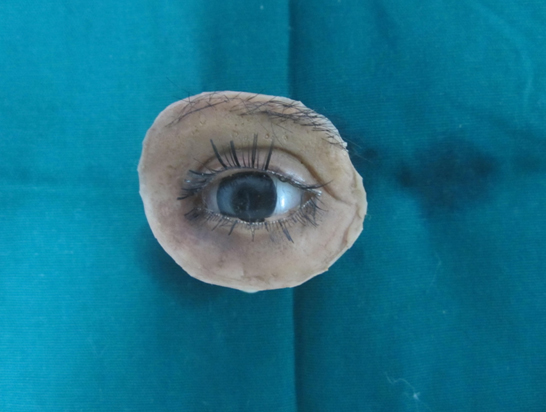
Figure 13. Eye lashes and eye brows incorporated in the silicone prosthesis.
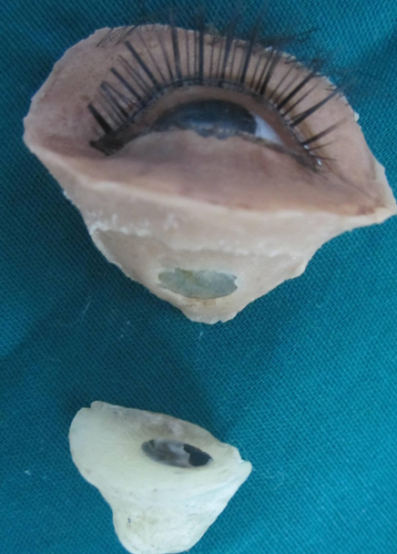
Figure 14. Final Prosthesis.
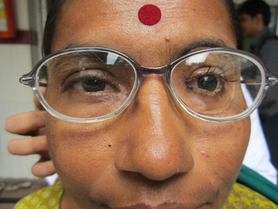
Figure 15. Prosthesis in place.
Discussion
The rehabilitation of the orbital defect is a complex task, and if reconstruction by plastic surgery is not possible or not desired by the patient, the defect can be rehabilitated by an orbital prosthesis, improving the aesthetics and instilling confidence to face the society with dignity. Various methods of auxiliary retention for orbital prostheses include eyeglasses [8], engagement of hard and soft tissues undercuts [8,9], magnets [8-10], adhesives [8], combinations of the above [8-10], and osseointegrated implants [11]. Although osseointegrated implants may provide the most reliable prosthesis retention; additional surgeries, expenses, inadequate bone, and prior radiation to the area may contraindicate this type of treatment [8]. Modern prosthetic replacements are secured with adhesives that are readily available, easily applied, and provide satisfactory retention for a limited period of time. However, continual use of adhesives may cause allergic response or irritation [9]. Conventionally retained orbital prostheses are practical, trouble-free, cost-efficient, and successful. The most commonly used conventional method to retain orbital prostheses is the eyeglass frames and anatomic retentive undercuts [12].
This article describes the rehabilitation of an orbital defect using a two piece silicone and acrylic prosthesis, wherein retention has been achieved by a combination of anatomic undercuts and magnets.
In the present case, naturally occurring undercuts were evident in the superior and inferior portions of the orbital rim. Mechanical modes of retention by engaging these undercuts and further by using magnets were planned. So the orbital prosthesis was essentially planned to be made in two parts. The first part was an acrylic stent used to engage the inferior undercut and the second part was the actual orbital prosthesis. The two parts were oriented using magnets. In the present case, the sectional design of the prosthesis helped in engaging the naturally occurring undercut. The mechanical lock provided by the undercut and magnets offered good prosthesis retention and prevented accidental removal by dislodgment.
Conclusion
Loss of an eye is a very traumatic experience for an individual. Rehabilitation of such patients both emotionally and prosthetically is really a phenomenal task. Attention to detail is mandatory in each and every step to bring out a satisfactory end result. This clinical report details fabrication of a sectional orbital prosthesis for a female patient following enbloc removal of her left eye. The techniques employed greatly helped in increasing the retention of the prosthesis.
References
- Perman KI, Baylis HI (1988) Evisceration, enucleation, and exen-teration. Otolaryngol Clin North Am 21: 171-182. [Crossref]
- Stanley RB Jr, Beumer J 3rd (1988) Orbital rehabilitation: Surgical and prosthetic. Otolaryngol Clin North Am 21: 189-198.
- Lemon JC ,
Kiat-amnuay S,
Gettleman L ,
Martin JW ,
Chambers MS
(2005) Facial prosthetic rehabilitation: preprosthetic surgical techniques and bioma terials. Curr Opin Otolaryngol Head Neck Surg 13:255-62. [Crossref]
- Rodrigues S, Shenoy VK, Shenoy K (2005) Prosthetic rehabilitation of a patient after partial rhinectomy: A clinical report. J Prosthet Dent 93: 125-128. [Crossref]
- Shifman A (1993) Simplified fabrication of orbital prostheses using posterior attachment for the artificial eye. J Prosthet Dent 69: 73–76. [Crossref]
- Jooste CH (1984) A method of orienting the ocular portion of an orbital prosthesis. J Prosthet Dent 51: 380–382. [Crossref]
- Alice Katz BS, Gold HO (1976) Open-eye impression technique for orbital prostheses. J Prosthet Dent 36: 88–94. [Crossref]
- Taylor (2000) Clinical maxillofacial prosthetics. Quintessence Publishing Illinois: 233–276.
- Beumer J, Curtis TA, Marunick MT (1996) Maxillofacial rehabilitation: prosthodontic and surgical considerations. Ishiyaku EuroAmerica, St. Louis: 377–453.
- Dumbrigue HB, Fyler A (1997) Minimizing prosthesis movement in a midfacial defect: a clinical report. J Prosthet Dent 8: 341– 345. [Crossref]
- Arcuri MR, LaVelle WE, Fyler E, Jons R (1993) Prosthetic complications of extraoral implants. J Prosthet Dent 69: 289–292. [Crossref]
- Parel SM (1980) Diminishing dependence on adhesives for retention of facial prosthesis. J Prosthet Dent 43: 552-560. [Crossref]