Introduction
In addition to providing knowledge to be added to existing methodologies, this theory reveals for builders and operators of high-power plant aircrafts a simple secret to having an aeronautical design in terms of desirable "cost x benefit" (economicity relation), considering CA ranging from 1.33 to 6.89 - originated from the vision of "energy per mass”. Up to now the calculation of power plant to be installed in an aircraft is done empirically, despite all aeronautical knowledge, technical and scientific resources available. Then, the explain for continuous need using wind tunnels and/or lift software support.
The word “economicity”, considered neologism in some languages, translates the quality of everything that is economical. It is used to mean the reliable and economical operations of any activity, and so on, with the least possible cost. Therefore, refers to the correct management of the means in all activities, such as commerce, industry, services, governmental institutions and/or organizations, etc., because the activity must be done at the lowest cost and, thus, achieve its goal. Notice that the idea of “well manage” is directly linked to labor, time, money, and others, regarding the activity.
In a broader concept it is said that “economicity” is the practical and systematic administration of operations from an entity, project or public company, ensuring minimum operational costs for its functions assigned may be performed efficiently and/or effectively.
In “aviation” the results of efficiency and of effectiveness are reached in different ways due to the type of employment of aeronautical equipments. It means to say in case of “air operations” that the expected results will be: sometimes of “efficiency”; and/or; sometimes of “effectiveness”. Necessarily, both results must be reached by observing the “flight safety”.
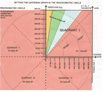
With those opening remarks, we believe that: - with reference to commercial aviation the immediate concern is efficiency - (see “green sector” of Standardized Geometric Application of CA- figure 1-21), i.e., the commercial flight operations require aeronautical equipments that work with lower costs. For instance: with the lowest fuel consumption for transporting passengers and payload, so that such operations be profitable and can occur with maximum “flight safety”, since this type of aviation does not use radical maneuvers; - with reference to military aviation the most important objective is the fulfillment of “flight mission”, disregarding “higher costs” because the aimed results are reached for any price, that is, effectiveness - (see “blue sector” of Standardized Geometric Application of CA - figure 21) - because such air activities require greater performance and radical maneuvers of the involved aircrafts, as flights of types: nosedive, air combat, looping, screw, tounneaux, inverted flight, etc., and, of course, never neglecting the item “flight safety”.
Methodology
Hence, our theory validates the practical side of Santos Dumont when, at his time (1906/1907), due construction of 14Bis, Project 15 and other models of Project Demoiselle, he disregarded the “wing load” with the intention to add another mathematical relation, i.e., “mass (kg) per energy (hp)” (I), to provide a dimensionless numerical result, since in modern times the normal thing is consider the relation “energy (lbf) per mass (tone)” (II). Notice whats is contained in (II) does not invalidate the practical side of Santos Dumont. Then, how is it explained in the previous paragraph? It is explained as presently, as historically. In other words: because the contained in (II), the relation “energy/mass” is associated to modern aircrafts that have jet engines – more powerful motors and of high consumption; and because in (I), the relation “mass/energy” refers to its historical usage, that is, it relates to aircrafts having propeller engines (whether conventional engines or turbopropeller engines). This leads us to do a mathematical two-dimensional cartesian relation, involving MTOW (maximum takeoff weight, in kilograms, Δy=kg), divided by the POWERPLANT (power delivered by the engine, in hp or shp, Δx=hp ou shp), to result in an Angular Lift Coefficient - CA:
tg Ɵ = sin Ɵ ÷ cosin Ɵ = Δy ÷ Δx = m = Ca = CA
Therefore, the relation “mass/energy” refers, historically, for aircrafts with engines less potent, type traction (in hp/shp). This traction, type “pull” propulsion and/or "push" propulsion, on a propeller aircraft, depends on the efficiency of it (ηp), because it expresses “how much power the engine delivers”, to be converted into force of propulsion.
At the time of Santos Dumont nobody dreamed of jetpower, like “thrust (lbf)” because himself and his contemporaries only paid attention to the mathematical relation “MASS/ENERGY”, like “kg/hp” - because in no way compromises any calculation when used in order to obtain an “Angular Lift Coefficient CA”, i.e., a dimensionless number to identify efficiency and/or efficacy for all types of aircrafts in the world, if jet aircrafts and/or if propeller aircrafts, both types consuming liquid fuels.
I remember that “successes” (with takeoffs) and “failures” (no takeoffs) of Santos Dumont in aircraft construction, made him “intuit” the quotient “6” (or a quotient of “lower value”) to determine certain Angular Lift Coefficient - CA - in the mathematical relation:
“MASS (kg) / ENERGY (hp)”, and what is meant by: MTOW / POWERPLANT ≤ 6
...so that the aircraft could takeoff, that is, to gain lift. It is, as we would say technically and scientifically, on “intuition” and/or “practical side” of Santos Dumont that: “the aircraft after gaining the inertia (V0), and during the running of takeoff overcoming all drag (= resistance)", it will be able to obtain a desirable lift, (VLof), if the calculations shows a value of “6”, or a “lower value”, as an Angular Lift Coefficient of CA, resulting from:
m = CA = MTOW (kg) divided by POWERPLANT (hp) ≤ 6
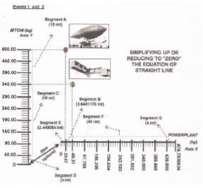
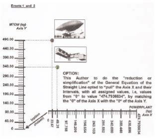
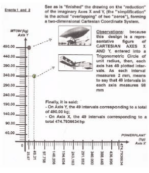
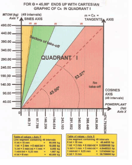
Obs.: The iconographic synthesis in Figure 1 portrays, initially, the image of a STANDARD CARTESIAN GRAPHIC OF CA which, on the other hand, will give place to the STANDARDIZED GEOMETRIC APPLICATION OF CA:

Figure 1: Trigonometric Circle
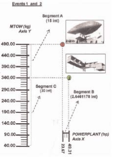
STANDARD CARTESIAN GRAPHIC OF CA - (Unit radius = 49 parts = 49 intervals)
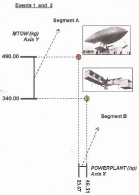
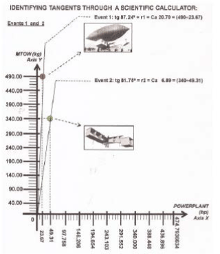
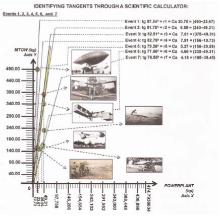
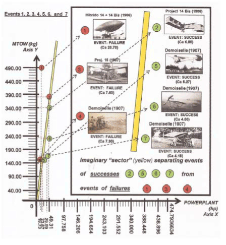
The registred numerical data, about weight and power from the first two "events" (aircraft construction) of Santos Dumont, are: (Obs.: see from Figure 2 to Figure 18; and for other events; and observe the development step by step).
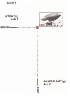
Figure 2: Reduced Geometric Scale
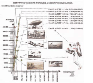
Figure 18: Geometric draw in different Scale
1st. Event = (failure = no takeoff) 2nd. Event = (success = takeoff)
MTOW = 490 kg; POWERLANT = 23.67 hp MTOW = 340 kg; POWERLANT = 49.31 hp
(will be better understood according to the following step-by-step geometric plotting in figure 2 and 3)
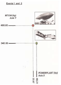
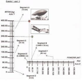
Figure 3: reduced Geometric Scale
3rd. Event = (failure = no takeoff) 4th. Event = (failure = no takeoff)
MTOW = 375 kg; POWERLANT = 49.31 hp MTOW = 156 kg; POWERLANT = 19.73 hp
5th. Event = (success = takeoff) 6th. Event = (success = takeoff)
MTOW = 156 kg; POWERLANT = 29.59 hp MTOW = 230 kg; POWERLANT = 49.31 hp
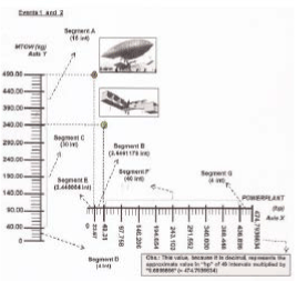
7th. Event = (success = takeoff) MTOW = 156 kg; POWERLANT = 29.59 hp
8th. Event = (success = takeoff; found in modernity) MTOW = 127 kg; POWERLANT = 95.42 hp
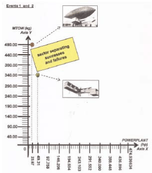
For framing the “STANDARDIZED GEOMETRIC APPLICATION OF ANGULAR LIFT COEFFICIENT, CA”, of any aircraft, (see figure 21), it is sufficient multiplying the values of each axis by a integer number, “a multiplier factor or number chosen”, preferably finished in “zero”, without decimal places, and, proportionally into both cartesian axes, for refered values in kg and in hp.
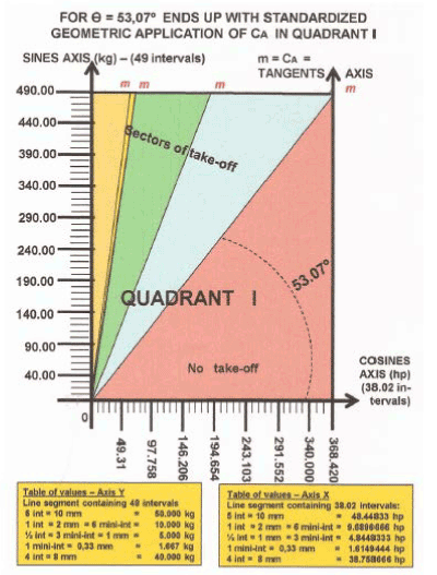
Figure 21: geometric draw, where each interval is equal to 2 mm:
Y Cartesian Axis has 49 intervals = 98 mm; X Cartesian Axis has 38.02 intervals = 76.04 mm
Notes: The X Axis is discontinued after the value “368.42”, yielding Standardized Geometric Application of CA, and, therefore, in compliance with the results for CA = 1.33 because it is not known in the aeronautical world hp values greater than “368.42” to meet the mathematical relation CA = kg per hp
So, the new resulting values represent the technical specifications of “MTOW” and “POWERPLANT” to the considered aircraft designer and that, therefore, such values will larger than the values of “MTOW” and “POWERPLANT” listed originally in the STANDARDIZED GEOMETRIC APPLICATION OF ANGULAR LIFT COEFFICIENT – CA
The Author himself, by his particular convention, as shown in the Figure 22, offers a “table of operational costs” – of efficiency & effectiveness – depending on the ANGULAR LIFT COEFFICIENTS - CA, previously defined:

Figure 22: (standardized geometric application designed in different scale)
Buyer of Aircrafts
All aircraft manufacturer is obliged to give clear answers to any buyer, as a particular buyer, commercial company, military organization, etc., to meet key requirements of “efficiency” and/or “effectiveness” and also the following questions, i.e., what the certificated aircraft will be able to: if the aircraft will fly fast, how much it goes far, if its flight range attends the objectives, which runway length will require, if it climbs rapidly, if it takes much time to reach the cruise altitude, and so on. Notice that following questions will be answered by the aerodynamic forces acting on the considered aircraft. However, we believe that together with the key requirements, it should be placed in an another “first” question, named:
“how truly all flights begin”
...we answer: “the flight begins by the performance at the stage of takeoff roll". So, let us see how the takeoff of a certificated aircraft occurs. For example: a aircraft of transport. On this one we must consider 8 "types" of speed at takeoff roll, as shown in Figure 23:

Figure 23: Angular Lift Coefficient CA
CD = drag coefficient; CL = lift coefficient = angular lift coefficient
In figure 27 – As the regulation of FAR PART 25 TAKEOFF, we have the following 8 types of velocity - (speed) - between the occurrences of the Drag Coefficient (CD) and Lift Coefficient (CL):
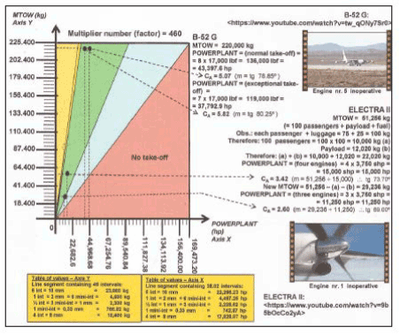
Figure 27: aircrafts that reffer to 2nd APPLICATION MODE
0 = V0 = “zero” velocity; inertia;
Vs = velocity that exceeds the stall velocity;
Vmc = minimum control velocity;
V1 = velocity of decision;
VR = velocity of rotation;
Vmu = minimum “unstick” velocity;
VLof = lift-off velocity;
V2 = climb velocity up to 35 feet.
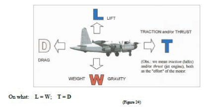
Therefore, there are four aerodynamic forces acting on an aircraft: (Figure 28)
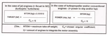
Figure 28: Angular Lift Coefficient CA
Lift, Weight (Gravity), Traction/Thrust, Drag
Looking again at Figure 22 - (costs) - and knowing: the type of propulsion used, the devices of hyper lift, etc.; the designer should consider an Angular Lift Coefficient CA on takeoff, resulting from the weight (kg) divided by horsepower (hp), since the pilot is required to accelerate his aircraft from speed “V0” to achieve the speed “V2”, (as shown by Figure 23), when he must use the maximum 2/3 of available runway for takeoff (TORA = takeoff roll available) and thus to reach an operating cost ranging from “maximum efficiency” to “maximum effectiveness”, (as we have already seen in Figure 22), to demonstrate certain profitability in the mathematical relation “COST x BENEFIT”, according to an Angular Lift Coefficient CA, ranging from 6.89 to 1.33
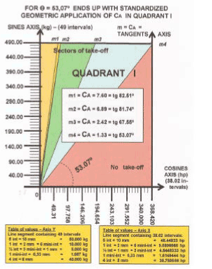
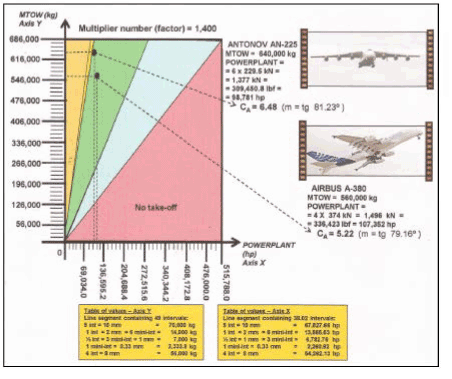
1st APPLICATION MODE - We see for the geometric application, (Figure 25), from the fragile 14Bis till the largest commercial aircraft, the A-380, and also considering the most robust cargo aircraft of our days, the AN-225, the relation “cost x benefit” is identified by four sectors limited by different declivities “m”:
m1, m2, m3, m4 = CA (angular lift coefficients)
So, representing the declivity “m” of tangents of the following four angles:
82.510 (m1 = CA 7.60) ; 81.740 (m2 = CA 6.89) ;
67.550 (m3 = CA 2.42) ; 53.070 (m4 = CA 1.33)
Standardized Geometric Application of ca
The geometric application in Figure 25 is not mandatory. However, it is a geometric solution to identify quickly and preliminarily if the aircraft industry is making an efficient aircraft or an effective aircraft, according to its MTOW (= maximum takeoff weight, value in kg), divided by its POWERPLANT (= installed power, value in hp).
Examples of aircrafts that reffer to 1st APPLICATION MODE: An-225; A-380 (factor or number multiplier chosen = 1,400) (figure 26)
2nd APPLICATION MODE - The Application has another peculiarity: identifying aircrafts of 3 engines, of 4 engines, or aircrafts of more engines that can takeoff with one (1) inoperative engine, making flight maintenance at their bases of operations. Obviously, this flight should be regulated by the following:
1) Only using the required amount of fuel to consume in the flight route; and, therefore, without passengers and without payload
2) Special authorization for takeoff, and with minimum crew;
3) To fly with good meteorological weather, expected on the route;
4) Soil (ground) for takeoff must be greater than expected for a normal takeoff;
5) In the case of turbo propeller aircraft, of four engines, the position of inoperative engine must be considered, because of the torque resulting from the engine "further away" of the fuselage; etc
Examples:
- three-engine aircrafts that can takeoff with one inoperative engine: XF-88B; FALCON 900
- four-engine aircrafts that can takeoff with one inoperative engine:
ELECTRA II; C-130; SUPER CONSTELLATION; VC-90; BOEING 707-320-B; etc.
- eight-engine aircraft that can takeoff with one inoperative engine: B-52G
As such exceptional situations are very rare to happen, let's take just two examples identified by the STANDARDIZED GEOMETRIC APPLICATION OF CA: ELECTRA II and B-52G, exactly because we can document these types of takeoffs with videoclips - (check on URL addresses on Youtube by typing the following):
ELECTRA II: <https://www.youtube.com/watch?v=9b5bOcCo2yA> B-52G: <https://www.youtube.com/watch?v=tw_qONy7Sr0>
Examples of aircrafts that reffer to 2nd APPLICATION MODE: ELECTRA II; B-52G
(chosen factor or multiplier chosen = 460) (see figure 27)
Returning to the idea of “economicity”, it appears that in both Aviations, (Commercial
& Military), the relation “mass/energy” in takeoff roll requires a dimensionless value type m =
Ca = CA ≤ 6 to represent an ANGULAR LIFT COEFFICIENT CA, as being a new and important acceptable data, preliminarily, in calculation of powerplant of the airfoils developed as designs of aircrafts consuming liquid fuels.
As we have seen, such value is obtained through a "STANDARDIZED GEOMETRIC
APPLICATION OF CA”, developed trigonometrically (Figure 21), from:
m = Ca = CA = declivity = tg ɵ = sine ɵ ÷ cosine ɵ
using data of MTOW (maximum takeoff weight in “kg”, Y-axis), divided by POWERPLANT (horsepower in “hp”, X-axis).
The values that caused the quoted data were written by Santos Dumont during his activity of aircraft manufacturer in the years 1906 and 1907, when he did not have to worry about the "wing load", due to his "practical side”.
Another point to be observed due Figure 23, as to remember: it is the factor 0.3191362 or with four decimal places 0.3191 (*)
(*) This Author considering that the VLof normally ranges from 100 kt to 120 kt, chose the velocity 107 kt as median value of VLof for didatic purposes, depending on the following way to calculate “power”:
P POWER hp = F FORCE (lbf) x V VELOCITY (VLof in kt)
as <http://en.wikipedia.org/wiki/Horsepower>
Having up
1 hp = 33.000 lbf x ft/min = 745.699881448... (the most accurate decimal approximation) And still: 1 hp = 335.28 lbf x kt
Hence, becoming lbf for hp:
VELOCITY (VLof in kt) 107 kt
FORCE (thrust lbf) x = thrust lbf x =
POWER (1 hp) 335.28 x kt
= thrust lbf x 0.3191362 = POWER (hp)
Thus, in jet aircrafts, if we want to convert lbf (thrust force) to hp (horsepower force), and considering that the result is for the didactic development of this theory, it was necessary to consider a velocity VLof measured in knot (= nautical mile per hour). So, didactically, this Author considered 107 kt (= 198 km/h) as a medial value of VLof (LIFT-OFF VELOCITY) acording to the following formulation of horsepower P (hp):
F (lbf ) x 0.3191362 = P (hp) or with 4 decimal places: F (lbf ) x 0.3191 = P (hp)
Conclusions - (five conclusive topics)
1st Conclusive Topic: (mathematical relations)
As the relations “ENERGY/MASS” (1.1) and “MASS/ENERGY” (1.2) differ themselves:
(1.1) the relation "thrust (lbf)/weight (tone)" (ENERGY/MASS) – is, nowadays, associated to engines of jet aircrafts, because they have most power and high consumption;
(1.2) the relation “weight (kg) / power (hp)” - (MASS / ENERGY) – is, historically, used by aircrafts with propeller engines, (whether conventional engine, or turbopropeller engine). Therefore refers to cartesian relation type between the “maximum takeoff weight” (kg), divided by “powerplant” (hp). I mean: the “powerplant” delivered by the motor, resulting an
ANGULAR LIFT COEFFICIENT: m = Ca = CA = ∆y ÷ ∆x
Thus, the traction – propulsion "pull" and/or propulsion "push" – of a propeller aircraft depends on the propeller efficiency (ηp), expressing "how much horsepower the engine delivers", in order to be converted into propulsive force.
Although at the time of Santos Dumont nobody had dreamed of jetpower type “thrust (lbf)”, just because he and his contemporaries only paid attention to the relation "MASS/ENERGY" type “kg/hp”, in nothing this mathematical relation compromises any calculation when used for obtaining an “angular lift coefficient”, which becomes identifier of a dimensionless number for efficiency and/or efficacy for all types of aircrafts in the world, be jetpower aircrafts, or be turbopropeller aircrafts, consuming liquid fuels.
2nd Conclusive Topic:
(This topic consists of 4 subtopics)
- (2.1) it is known that takeoffs of all modern aircrafts occur in function of ANGULAR LIFT COEFFICIENTS CA – during the roll on the soil (ground) which influences directly in VLof, regardless the consumeption of liquid fuel (gasoline or kerosene), to represent economy in the "operating costs". Therefore, between the CD and CL exists a CA to be considered atypically in the modern aircrafts which can be designed to takeoff with a given group of engines installed - powerplant - in order to fly efficiently and/or effectively, due the relation "cost x benefit".
- (2.2) by convention, and because of flight safety, THE MOST EFFICIENT AND
“MAGICAL” ANGULAR LIFT COEFFICIENT, (CA), assumes a scientific value, ie, the value “6”. Note that this theory treats the subject scientifically and, despite historical reasons, consider it in a conservative view. This last reason makes the value “6”, be qualified as “magical” (a "pure" number intuited by Santos Dumont).
- (2.3) it is observed that, due to the existence of various Angular Lift Coefficients CA during takeoffs, which the numerical values deducted within a conservative approach vary between 6.89 and 1.33 and, whose operability in roll on the ground should be given due the relationship “COST x BENEFIT”. Thus, it is possible to verify the existence of certain technical and financial adequacy: the operating COST (= efficiency cost and/or effectiveness cost) versus BENEFIT (= flight safety), mainly due to the liquid fuels used by the operator - (gasoline, kerosene, biofuel).
- (2.4) we must agree, for effect of this theory, there are two types of "remarkable aircrafts":
- (2.4.1) on those single-engines rare and/or twin-engine aircrafts, that takeoff with Angular Lift Coefficients range between 7.60 and 6.90; and;
- (2.4.2) aircrafts having three, four or more engines that, without payload and/or without passengers, are able to takeoff with one inoperative engine if their Angular Lift Coefficients of CA rang between 6.89 and 5.00 (green sector).
3rd Conclusive Topic:
As long as there is empiricism in the calculation of an installed powerplant, its Angular Lift Coefficient CA will be, preliminarily, a valuable number so designers of modern aircrafts reach a more exact mathematical solution as possible in determining the powerplant, in order to guarantee the flight safety during the most critical time of the aviation activity, which is th e running takeoff on the ground. As consequence, we can design today an aircraft with the structural mass that we want and, knowing the projected weight, search with absolute certainty a group of engines (motorization) on international engine market to have safety during takeoffs, i.e., made with efficiency and/or effectiveness (sectors “green and blue”, defined by Angular Lift Coefficients, (CA), (see Figure 22).
4th Conclusive Topic:
Regarding "flight safety", and as the logic of this theory identifies an Angular Lift Coefficient
CA in horizontal running takeoff of piston aircraft and/or jet aircraft, we may also say there is a CA atipically between the V0 and the VLof, when preliminary answers are suggested by the theory for aircraft manufacturers, in order to estimate “how much power to be delivered per engine” to be installed on the project. So, in that sense, the preliminary answers can be given by the following two formulas: (Figure 28)
An aeronautical project developed by an installed aircraft industry anywhere in the world, will have its resultant Angular Lift Coefficient, CA, to obey one of the two following formulas, so it can fly with efficiency or effectiveness in the expected and wanted way of "safety" mode:
5th Conclusive Topic:
(This topic consists of 3 subtopics)
(5.1) Environmental preservation
The theoretical framework of this theory predicts, with its five conclusive t opics, an updated
contribution (not mandatory) formed by preliminary solutions for aeronautical engineering and, in parallel, to engineering in general, for economies of governments and for the geopolitics of oil, and, of course, that everyone should rethink about what is more important today: the preservation of the environment for future generations to ensure their survival with quality of life, without suffering serious impacts and in compliance with a desirable ratio of "cost versus benefit" because of the ecosystems are being damaged every day, so the planet will no longer be habitable.
Thus, the LIFE as universal principle of survival for living beings should be regulated by the importance of INTERNATIONAL ORGANIZATIONS, through their leaders and their respective governments, in the management of international relations: political, economic, social and environmental, among others, so that a "positive minimum diary" can be established to ensure the sustainability of the planet, despite the various projects of different interests, that is, political, economic, architectural, etc.
The unbridled consumption of fossil fuels is the major cause of emission of Carbon Dioxide (CO2) in the Earth's Atmosphere. Besides this greenhouse gas in the atmosphere, also, the effects occur for Methane Ozone (CH4) and for Nitrous Oxide (N2O).
This finding requires priority actions of Heads of State representing the largest economies in the world, to discuss the ecological disasters, so that international agreements signed to reduce the emission of greenhouse gases may not be mere signed protocols, simply for people to see.
See that global warming is directly linked to the greenhouse effect, making the year 2014 (since 134 years before) the hottest telluric history, even though the El Niño phenomenon didn’t happen. The planet has exceeded the tolerable limits of its own extinction due to increasing of carbon dioxide in atmosphere. In this catastrophic sense it should be also considered the disordered deforestation and contamination of rivers, seas and oceans by chemical fertilizers and other untreated sewage.
(5.2) A product derived from petroleum, used as Aviation Fuel, to exhaust itself in the lithosphere
This theory provides an academic discussion capable of calling the attention of all those involved in oil production, in particular with regard to aviation kerosene, in the sense that the responsible world authorities by sustainability of the planet, understand the need to be rethought the environment with great care and more effective treatments, therefore, aircraft opera tors and turbine manufacturers for jet aircrafts should sit at the negotiating table to rethink courageously the "retirement" of “turbojet” engines. In other words: on total replacement of engines “turbojet” by “turbofan” ones.
These “turbofan” engines are by far much more economical in terms of operational consumption of fuel, and for having less polluting characteristics of vital atmosphere. It is therefore imperative that the aeronautical industries make their "next and future" projects, I say better, "current" projects, especially the jet aircraft projects, in a way these generations of flight equipments be environmentally sustainable, at least, incorporating turbofan turbines.
The aeronautical engineering is aware that the engine is the heart of an aircraft and its choice is considered of vital importance to the success of an aircraft project. Therefore, a right choice will represent the care attention to these two principles: the "principle of economy", which means lower fuel consumption and lower maintenance costs”; and the “principle of ideal operating", that means less noises and less pollution. So, the technical choice of an engine is complex, and should be precise for the success of considered aeronautical design.
I believe that the existence of a system type “turbofan”, a sort of large fan running at a lower speed than the compressor, thus increasing the internal air circulation inside the engine, it seems now as the “first best solution”. Although I am not expert on the subject, but as an aviator who I have been during 50 years of air activity, flying 8,000 hours as pilot in command, I repeat that: THE “TURBOFAN” SOLUTION IS DESIGNED FOR THE BEST EFFICIENCY OF AIRCRAFT: reducing noise and at the same time assuring the volume of gas emissions in the atmosphere will be minimized.
(5.3) Finally, the question that bothers
Which is the way to understand an energy matrix that produced a peak of 89 million barrels/day of petroleum in 2014 (see English Journal THE ECONOMIST / 2014) - (**), required for Humanity enjoy of air travel worldwide, in a total of 2,51 million flights/month, whose daily extraction of volume of barrels of oil, multiplied by the total of days "30", reveals an astonishing situation, as if the World Petroleum Industry makes huge 30 "holes"/month, each one of volume equal to the capacity of SUGAR LOAF HILL, in Rio de Janeiro, Brazil, (=14,151,000,000 liters of oil), giving us the feeling that these huge “holes” are dug inside the planet, (lithosphere), IF EVERY TIME that the active oil wells, and/or each time, others wells of petroleum in process of opening, PRODUCE more than the quoted size peak of oil production?
Petroleum Derivatives - Production versus consumption
In 2000 the International Energy Agency (IEA), in Paris, published an estimate stating that the known oil reserves would only be sufficient to meet the world's needs for about another 40 years, ie, up to the beginning of the decade “2040”, maintaining the rhythms of production and consumption of the time (year 2000), that were respectively 74,916 million barrels per day and 76,076 million barrels per day. It means that world consumption is higher than production: 76,076 ˃ 74,916 - It means, still, and with another approach, that consumption will at least have a “greater” progression than production, which is highly worrisome for the economy, because, for example, the production of Aviation Kerosene - JET A1 - does not track the consumption of jet and turbopropeller aircrafts around the world.
If, one (1)) barrel of oil, (containing 159 liters of crude) produces about eleven (11) liters of JET A1, so, let's take just one flight example: an Airbus A-380 (which is one of the most economical jets), with a range of 15,700 km and that, to takeoff daily from Dallas in the State of Texas-USA to Sydney in the State of New South Wales-AUSTRALIA, flying nonstop for little more than 17 hours at a speed of 900 kmh, must have its maximum capacity of fully serviced fuel, which will be 323,546 liters of JET A1, for that flight can be performed in compliance with the International Instrument Flight Rules, (IFR), in the same way as they occur with thousands and thousands of daily flights between five continents: Dubay / New York; Melbourne / Los Angeles; Tokyo / San Francisco; etc., etc.
By a simple “rule of three” it is noted that 29,413 barrels of crude oil are needed to serve the “Dallas / Sidney” flight because these 29,413 barrels of crude oil are the minimum required to produce 323,546 liters of JET A1. Is the IEA warning worrisome or not?
Considering that we are in the year 2016, and due to the IEA warning, it is concluded that in a further 24 years the Jet and Turbopropeller Aviation will suffer from JET A1 worldwide. It means that: If “Jet and propeller Aviation stops”, then “the world will stop.”
(**) see graph in: http://www.resistir.info/peak_oil/global_oil_risks_mar12_p.html