Abstract
Low-grade ilmenite can be leached with concentrated HCl at atmospheric pressure and at 80oC. After filtration to separate insoluble matter the solution containing TiO2+ and Fe2+ is heated to precipitate titanium hydroxide and recover HCl. The titanium hydroxide is then calcined to synthetic rutile containing 95+%TiO2 while FeCl2 is subjected to oxyhydrolysis or fluidized be to recover HCl and Fe2O3. The process naturally can be applied to high grade ilmenite. It bypasses electric furnace process which applies only to high grade ilmenite and is superior to the sulfuric acid process which is highly pollutant. The product of this process can be used to prepare the white pigment as well as titanium metal.
Keywords
HCl leaching, Magpei process, Synthetic rutile, Oxyhydrolysis, Electric furnace, Chlorination, Sulfuric acid process
Introduction
The major titanium minerals are rutile, TiO2 and ilmenite, FeTiO3 (Figure 1 and 2). Rutile is easy to process to titanium metal or TiO2 pigment by the chlorination method while ilmenite is more complicated because of its high iron content. Since the world reserves of titanium are 90% in the form of ilmenite and only 10% in the form of rutile, the treatment of ilmenite is evidently an important question in metallurgy [1,2].
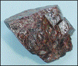
Figure 1: Museum sample of rutile, ~ 90 % TiO2
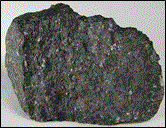
Figure 2: Museum sample of ilmenite, FeTiO3 (59.4 % TiO2)
Ilmenite deposits may be massive as in Province of Quebec (Figure 3) or as black sands (Figure 4) associated with magnetite, monazite, and other valuable minerals which are separated by physical methods (Figure 5). In the first magnetic separation a weak magnet is used to separate magnetite while in the second magnetic separation a high-intensity magnet is used to separate ilmenite.
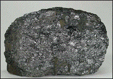
Figure 3: A sample of massive ilmenite of Quebec

Figure 4: Black beach sands as in India
Early methods for pigment production
In 1916, the Titanium Pigment Corporation of Niagara Falls, New York and the Titan Company of Norway simultaneously began commercial production of this new white pigment. Then, the principal white pigments used in paints were white lead, zinc white, and lithopone. In this method ilmenite was treated with concentrated H2SO4 at 110–120°C to form ferrous and titanyl sulfates:
FeTiO3 + 4H+ → Fe2+ + TiO2+ + 2H2O
The reaction is conducted in large concrete tanks lined with acid resisting brick (Figure 6), heated by direct injection of high pressure steam or in a pug mill (Figure 7) [3]. The solidified mass produced in the reactor at the end of the reaction was then discharged from the reactor by dissolution in water or dilute acid. After removing the insoluble residue by filtration, the solution containing 120–130 g/L TiO2 and 250–300 g/L FeSO4 was concentrated under vacuum at 10°C to crystallize FeSO4·7H2O which was then centrifuged. Titanium oxide is then precipitated from solution by dilution and seeding resulting in the formation of dilute H2SO4 for disposal (Figures 8 and 9). However, the largest producer of pigment in Salvador, Brazil still uses this technology because it disposes the waste products in the ocean which are removed by the tide.
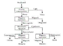
Figure 5: Beneficiation of black sands to recover its valuable components

Figure 6: Large concrete tanks lined with acid resisting brick
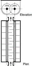
Figure 7: Heated pug mill
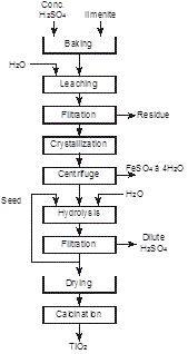
Figure 8: Production of TiO2 pigment by the sulfuric acid process
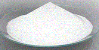
Figure 9: Titanium white, ~ 100% TiO2
Chlorination method
DuPont in USA [4] produces the pigment since 1950 by direct chlorination of ilmenite ore, separation of products by fractional distillation, then oxidation of TiCl4 (Figure 10):

Figure 10: Simplified Du Pont process for pigment production from ilmenite
2FeTiO3 + 7Cl2 + 3C → 2TiCl4 + 2FeCl3 + 3CO2
TiCl4 + O2 → TiO2 + 2Cl2
The problem of this process is recovery of chlorine from ferric chloride or marketing the large amounts of this co-product.
Separation of iron
Because of the pollution problems associated with the disposal of dilute sulfuric acid and FeSO4, iron in the ore is separated at an early stage. This is achieved in two ways: by electric furnace and by hydrometallurgical routes.
Electric furnace process
The electric furnace method was developed in 1950s [5]. The ore was mixed with a certain amount of anthracite which was just enough to reduce the iron oxide component of the ore, then charged in an electric furnace at 1 650°C where iron oxide is reduced to metal while titanium is separated as a slag (Figure 11). The reactions taking place during reduction are the following:
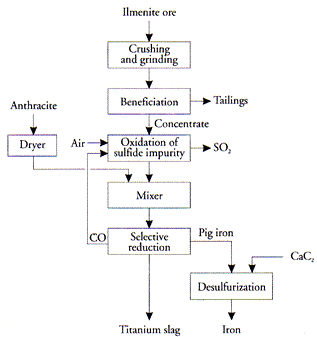
Figure 11: Electric furnace process for iron separation
FeTiO3 + C → Fe + CO + TiO2(slag)
Fe2O3 + 3C → 2Fe + 3CO
This method is used by the Rio Tinto QIT at its plant in Sorel near Montreal and at Richards Bay in South Africa. It is also used in the Soviet Union at Zaporozhye (Ukraine) and in Japan.
Titanium slag is mainly iron magnesium titanate, (Fe,Mg)Ti4O10, and a small amount of silicates; typical analyses is 72–85% total TiO2. A small amount of TiO2 is reduced to Ti2O3. The reduction of the iron oxides is not taken to completion so that some iron oxide is left in the slag to decrease its melting point. Melting point of TiO2 1840°C and ilmenite 1435°C.
The slag is high in titanium and low in iron (Figure 12) and is therefore preferable to ilmenite in manufacturing TiO2 pigment or titanium metal. However, the slag produced in Quebec is not suitable for chlorination because of its high impurity level — about 16.6% as compared to about 6% in other slags [6]. These impurities will not only consume unnecessary amounts of chlorine but also will create a disposal problem. Furthermore, some of these impurities, e.g., calcium and magnesium will interfere with the chlorination process itself which is conducted at 800°C by forming a molten phase (CaCl2 m.p. 770°C, MgCl2 m.p. 708°C).
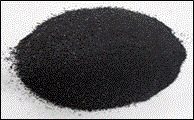
Figure 12: Ground titanium slag, FeTi4O10 (70-80 % TiO2)
For these reasons, titanium slag was used only for making pigment by the sulfuric acid process [7]. The slag was treated in the same way as ilmenite with the exception that no separation of ferrous sulfate was necessary because the bulk of iron was already separated by reduction in the earlier step (Figure 13). The sulfuric acid treatment process of the slag, however, still suffered from the disposal problem of the waste acid and as a result it was abandoned in the 1980s and replaced by a new technology based on upgrading the slag to 94.5% TiO2 by leaching away most of the impurities by HCl under pressure to render it suitable for chlorination.
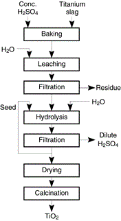
Figure 13: Leaching of titanium slag for production of TiO2 pigment, now obsolete
The hydrometallurgical route was developed in 1960s and involved leaching of iron from ilmenite and obtaining a residue rich in titanium (90–95% TiO2) known as “synthetic rutile” [8]. In one case, the Altair process, a pigment grade TiO2 was obtained. All these processes use an oxyhydrolysis process for treating ferrous chloride to get HCl for recycle and Fe2O3 as a by-product.
High-pressure method
In this method, high grade ilmenite is decomposed in autoclaves by 20% HCl at 120°C and 200 kPa; iron is solubilized as ferrous chloride leaving a solid containing about 95% TiO2 which has the chemical analysis to rutile that us why it called synthetic rutile (Figure 14):
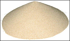
Figure 14: Synthetic rutile
FeTiO3 + 2H+ → TiO2 [impure] + Fe2+ + H2O
Low grade ilmenite cannot be treated by this method since all silicates and insoluble matter will contaminate the product. The synthetic rutile is then treated by chlorine to prepare TiCl4 from which TiO2 or titanium metal are obtained without pollution problems. The process is used in the USA, England, Japan, Taiwan, and Australia. Oxyhydrolysis could be conducted in a variety of ways as described below.
Atmospheric process
In 2014 it was found by Magpie Incorporation in Canada [9] that low grade ilmenite can be dissolved at 80°C with concentrated HCl at atmospheric pressure. After filtration to remove insoluble matter, the solution is distilled to recover HCl and to hydrolyse titanyl ion to TiO2. After filtration, the residue is calcined to produce synthetic rutile (Figure 16):
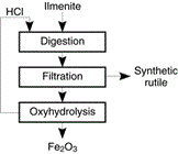
Figure 15: Production of synthetic rutile from ilmenite
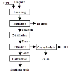
Figure 16: Production of 98+% TiO2 from a low-grade ilmenite [Magpie process]
FeTiO3 + 4HCl → TiO2+ + Fe2+ + 4Cl– + 2H2O
TiO2+ + 2Cl– + H2O → TiO2 + 2HCl
It is evident that the new leaching technology at ambient pressure is superior to the old electric furnace smelting–autoclave upgrading.
Oxyhydrolysis
Ferrous chloride solution is regenerated to HCl and Fe2O3 by oxyhydrolysis:
2FeCl2 + 2H2O + 1/2O2 → Fe2O3 + HCl
It is the same technology that is used for treating pickle solution. Two methods are used
Fluidized-bed oxyhydrolysis
In a fluidized-bed reactor the ferrous chloride solution is introduced onto a large bed of hot ferric oxide where heating is provided by the hot fluidizing combustion gases (Figure 17). As the combustion gas flows through the well agitated bed of oxide it quickly reaches thermal equilibrium with the bed. The solution is fed on top of the bed of oxides. The liquid feed wets the outer layer of the hot oxide particles and is quickly evaporated to form an onion-like layer of new solid oxide on top of the existing oxide, thereby producing dense homogeneous particles.

Figure 17: Fluidized-bed reactor for oxyhydrolysis of ferrous chloride
Spray roaster oxyhydrolysis
In this type of oxyhydrolysis roaster, the ferrous chloride solution is sprayed into an empty cylindrical vessel, while the required energy is supplied by the up flow of hot gases generated in the bottom burners (Figure 18). Spray roasters have large diameters to keep the gas velocities low. If the gas velocity is high, too many particles are elutriated with the off-gas, and the product quality and the efficiency of the roaster drop. The off-gas and oxides leave the roaster counter-currently at about 400°C to 500°C. The residence time of the sprayed particles in the high-temperature reaction zone is very short; therefore, very small liquid droplets, which can be quickly heated, should be created by atomization. The fast heat-up results in the formation of a solid oxide crust on the surface of each droplet. As the bulk of the droplet heats, the water content vaporizes and breaks through the oxide shell. Therefore, the spray roasted oxide is composed of very fine “fluffy,” hollow spheres.
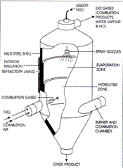
Figure 18: Regeneration of HCl from ferrous chloride solution by oxyhydrolysis in spray roaster
Production of titanium
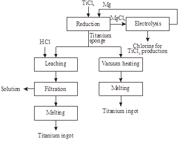
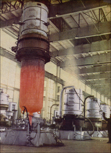
Metallic titanium is produced by chlorination of rutile, synthetic rutile, or titanium slag then reduction in a metallothermic reactor of TiCl4 by magnesium to titanium (Figures 19 and 20) [10]:
TiO2 + C + 2Cl2 → TiCl4 + CO2
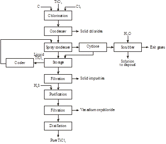
Figure19: Production of TiCl4 from rutile, synthetic rutile, or titanium slag
.</p>
<img src=)
Figure 21: Metallothermic reactor being removed from furnace
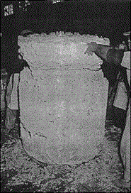
Figure 22: Titanium sponge (top) and MgCl2 (bottom) removed from the reactor
References
- Barksdale J (1966) Titanium, Its Occurrence, Chemistry and Technology, Ronald Press, New York.
- Sibum H (1997) “Titanium”, pp. 1129-1179 in Handbook of Extractive Metallurgy edited by F. Habashi, published by WILEY-VCH, Weinheim, Germany.
- Habashi F (1993) A Textbook of Hydrometallurgy (2ndedtn). Métallurgie Extractive Québec, Québec City, Canada.
- DuPont (2007) Brochure™ Ti-Pure® titanium dioxide.
- Habashi F (2002) Textbook of Pyrometallurgy, Métallurgie Extractive Québec, Québec City, Canada.
- Toromanoff I, Habashi F (1985) Transformation of a Low-Grade Titanium Slag into Synthetic Rutile Intern. J. Mineral Processing 15: 65-81
- Habashi F (1996) Pollution Problems in the Mineral and Metallurgical Industries, Metallurgy Extractive Quebec, Quebec City.
- Habashi F (1993) Pressure Hydrometallurgy (2ndedtn). Métallurgie Extractive Québec, Québec City, Canada.
- Habashi F, Kamaleddine F, Bourricaudy E (2015) A New Process to Upgrade Ilmenite to Synthet-ic Rutile Proceedings Conference of Metallurgists, Canadian Institute of Mining, Metallurgy, and Petroleum, Montreal. Reprinted in Metall 69: 27-30
- Habashi F (1993) Two Hundred Years Titanium. The Processing of Titanium Ores for Pigment and Metal Production. Arab Min J 11: 74-84


