Abstract
Finite element analyses have been carried out to investigate the effects of plaque thickness, plaque asymmetry and artery curvature on stent deployment in stenotic arteries. The Xience stent, one of the latest commercial metallic stents, was considered and its expansion was controlled by the inflation of a folded balloon. Results showed that it became a challenge to open arteries with thick plaque via stent expansion, as stresses and recoiling increased considerably with the increasing level of stenosis. Asymmetric plaque caused non-uniform stent expansion and uneven dogboning effect, with considerably high levels of vessel wall stresses developed in the regions covered by relatively thin layer of plaque. In a curved artery, a reduction in stent expansion was observed with the increase of artery curvature, accompanied by an elevation of stresses in the plaque and arterial layers. Consequently, particular care should be taken when implanting stents in diseased arteries with severe stenosis, unevenly distributed plaque layer and sharp curvature, as tissue damage might occur due to non-uniform expansion of the system.
Key words
stent deployment, finite element, stenosis, plaque asymmetry, artery curvature
Introduction
Angioplasty and stenting are predominantly used to treat cardiovascular disease such as coronary stenosis, a leading cause of heart attack. In the USA alone, around 425,000 percutaneous coronary interventions (PCIs) were performed per year between 2001 and 2009, of which about 382,000 cases involved the deployment of stents [1]. The worldwide coronary stent market is worth over $7 billion and forecast to grow by more than 5% annually [2]. In addition to coronary arteries, stents have also been extended for the treatment of a variety of human vessels’ obstructions such as peripheral arteries stenosis, brain aneurysms and blockages of tracheas and bile vessels.
So far, research on stents is largely centered upon the development of new materials and designs for better scaffolding, drug delivery and bioabsorbability, for which finite element (FE) method has been proved to be particularly useful in understanding the stent performance during and after deployment [3-5]. The majority of FE analyses of stent deployment, including the very recent ones, were focused on the mechanical behaviour of stents, i.e., expansion, dogboning, recoiling, stresses and fatigue failure. For instance, simulation of stent expansion was performed by Imani et al. [6] to study the effects of stent designs on arterial wall stresses and restenosis rate. For the three designs studied (i.e., Palmaz-Schatz, MultiLink and NIR stents), their results showed that Palmaz-Schatz stent generated the highest level of stress on the artery, specifically 15.6% more than MultiLink stent and 7.6% more than NIR stent. In clinical trials, Palmaz-Schatz stent showed the highest rate of restenosis, suggesting a strong correlation between artery wall stresses and restenosis rate. Schiavone et al. [5] carried out a detailed comparative study of Palmaz-Schatz, Cypher, Xience and Endeavor stents, and showed that stent design is one of the major factors in controlling stent expansion. In particular, stents with open-cell design (e.g., Endeavor) tend to expand more easily than those with closed-cell design (e.g., Cypher), but with higher recoiling effect. Dogboning effect can be reduced considerably for designs strengthened with longitudinal connective struts (e.g., Xience and Cypher). At a given deployment pressure, more severe deformation, stronger dogboning/recoiling effects and considerably reduced residual stresses were observed for stents made of materials with lower yield stress and weaker strain hardening. Demir et al. [7] proposed an FE-based method for designing and manufacturing bioabsorbable stents out of a magnesium alloy (type AZ31). Two-dimensional shape optimization with a morphing procedure was used to maximize the scaffolding capability of the stent without inducing excessive local large deformation. Using non-uniform rational basis spline parameterization, Clune et al. [8] carried out a shape optimization study of stents, aiming to optimize the fatigue resistance and radial flexibility of the device by FE modelling. Results showed that there is a trade-off between flexibility and fatigue resistance, and fatigue-resistant designs increase the potential of restenosis due to the excessive stiffness. Morlacchi et al. [9] studied the fatigue life of a stent and the influence of plaque calcification and cardiac wall movements on its failure. The model simulated the expansion of the stent inside the artery (with and without calcification) and post-deployment deformation subjected to cyclic blood pressure and wall movement. Their results showed that plaque calcification can be associated with an increased risk of stent fracture due to the increased stress on the stent mainly caused by the heterogeneity of the partially calcified plaque.
A recent study by Liu et al. [10] identified the pathological morphology of atherosclerotic blood vessels, such as tortuosity, kinking, coiling and severity of stenosis, using Magnetic Resonance Imaging (MRI) and computed tomography (CT) scan. Among 2,218 patients, tortuosity was found to be the most common abnormality, compared with kinking and coiling. Abnormalities were more common in extracranial arteries when compared to intracranial arteries, and no case of coiling and kinking was found in intracranial vessels. Out of a population of 434 patients, severe stenosis (70% and higher) was found in 26.5% of the patients, while 31.3% of the population exhibited intermediate level of stenosis (between 30% and 70%) and 42.2% of patients presented low level of stenosis (less than 30%). This highlights the importance of plaque and artery geometry, particularly the shape of the plaque and the tortuosity of the blood vessel, in stent deployment. For instance, Wu et al. [11] compared, but only briefly, stent expansion in curved and straight arteries, and showed that artery curvature tended to increase the stress levels on both the plaque and the arterial layers. Gu et al. [12] studied the arterial wall mechanics during stent deployment by considering an asymmetric plaque layer with an asymmetry ratio of 2:1 and an overall stenosis of 50%. The results showed that, in addition to stent design, plaque composition and non-uniform thickness due to its asymmetry significantly affect the stresses in the artery induced by stent deployment. An increase in plaque thickness or stiffness (e.g., plaque calcification) tended to reduce the stress concentration in the arterial layers. But work in this area is very scarce according to our literature search, and there is a serious lack of understanding about the effect of arterial factors on stent deployment and the potential damage to blood vessels caused by stenting procedure. Clinical reports proved that vessel damage is one of the main issues related to angioplasty and stenting, and high stress levels on the artery increase the chance of restenosis.
The aim of this paper is to simulate stent deployment in atherosclerotic artery with varied plaque thickness, stenosis asymmetry and vessel curvature, focusing on expansion of stent and stresses developed in the artery-plaque system. The simulation work is divided into three sections: (1) investigating stent expansion in arteries with stenosis varied between 40% and 60%; (2) comparing the effects of plaque asymmetry, with 7:3 and 9:1 asymmetric ratios, on stent deployment; (3) understanding the role of artery curvature, with 30° and 60° bends, in stent deployment. In all cases, the expansion behaviour and the recoiling and dogboning effects of the stent were compared systematically, along with the stresses in plaque and vessel layers, to elucidate the importance of vessel factors in stent deployment.
Finite element analysis
Stent model
Geometrical model of Xience stent was produced using Simulia Abaqus CAE according to the dimensions reported in open resources. The length of the stent was chosen to be 6 mm, the diameter at the crimped state was fixed at 1.5 mm and the strut thickness is 80 mm. The stent is made of cobalt-chromium alloy (type L605). The material was modelled as elastic-plastic with nonlinear hardening behaviour, for which the stress-strain curve was used as inputs in Abaqus. The stress-strain curve refers to the tensile test data for cobalt-chromium alloy, which were implemented in Abaqus by considering the increase of yield stress as a function of plastic strain [5,13].
Balloon model
The geometry of the balloon was produced using the design software package NX (Siemens PLM Software, UK), with a main diameter of 1.25 mm and an overall length of 10 mm. The cross section of the fully folded part was first sketched and then extruded by 8 mm. At both ends, the balloon gradually changed its cross section, over a distance of 1 mm, from the fully folded shape to a simple circle with a diameter of 0.75 mm. This was achieved using the sweeping tools of NX. Figure 1a gives a view of the folded cross section and the end of the balloon. The balloon was modelled as linear elastic, with a density of 1.1×10⁶ kg/mm3, Young’s modulus of 900 MPa and Poisson’s ratio of 0.3 [14].
Plaque-artery model
Blood vessel was idealised as a cylinder, with an outer diameter of 6 mm and a length of 40 mm. The healthy wall thickness was chosen to be 1mm, and consists of three tissue layers, i.e., intima, media and adventitia, with a thickness of 0.27 mm, 0.35 mm and 0.38 mm, respectively. The plaque layer is located inside the middle part of the artery, and has a length of 6 mm. The plaque thickness depends on the severity of stenosis and asymmetry. To cover the range of mild to severe vessel blockage [10], arteries with 40%, 50% and 60% stenosis were considered, corresponding to an inner diameter of 2.5 mm, 2 mm and 1.6 mm, respectively. Here, the percentage of stenosis was calculated as the ratio of the plaque thickness to the inner radius of a healthy artery. For the asymmetric plaque, an edge ratio, which is defined as the ratio between the maximum and the minimum thickness, of 7:3 and 9:1 was considered in this work, as illustrated in Figure 1b. This ratio is equivalent to the eccentricity index defined in [15], which was calculated to be 0.57 and 0.89 for the plaque with asymmetry ratio of 7:3 and 9:1, respectively. In order to produce a balloon-stent-artery model with curvature, Abaqus/Explicit simulations were first carried out by pushing the balloon-stent-artery system through a bended rigid guide which has the desired degree of curvature, i.e., 30° and 60° in this paper. The final geometrical model was then extracted from the output database, as shown in Figure 1b, and used for simulation of stent deployment in curved artery.
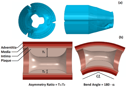
Figure 1. (a) Geometry of the folded balloon, showing the cross section of fully folded part and the balloon end; (b) Arteries with asymmetric plaque and curvature, with an illustration of asymmetry ratio and bend angle.
The constitutive behaviour for both artery and plaque (hypocellular) was described using the Ogden hyperelastic strain energy potential, with model parameters calibrated from test data [16,17]. The model was able to capture the dominant hyperelastic behaviour of the vessel and predicted the experimentally measured stress-stretch responses of vessel layers very well [16,17]. The model was also used successfully in our recent work to study the effects of design, material, coating and plaque composition on the mechanical performance of stent during deployment [5]. To be concise, mathematical and implementation details of the model are not repeated here and can be found elsewhere [5,17].
FE procedure
Using Abaqus CAE [13], stent was meshed into 111,680 first-order incompatible brick elements (C3D8I), with four layers of elements through both the thickness and the width of the stent strut. The incompatible brick elements (with full integration) were particularly used to accommodate large bending deformation of the stent strut. This is also strongly recommended by Abaqus for stent deformation simulation [13]. The balloon was meshed into 7,791 first-order quadrangular shell elements with reduced integration (S4R). Both the artery wall and the plaque were meshed into first-order hexahedral elements with reduced integration (C3D8R), and there are four layers of elements through the thickness of each arterial layer and eight layers of elements through the thickness of the plaque. Elements with reduced integration are mostly used for arterial layers to increase computing efficiency and numerical convergence associated with the large deformation nature of soft tissues. The artery and plaque systems had about 100,000 elements in total. An example of mesh is shown in Figure 2, including the stent, artery and balloon, for an artery with 50% stenosis and asymmetric plaque (ratio 7:3).
During the FE analysis, a uniform and linearly increasing pressure was applied to the inner surface of the balloon to simulate the inflation process, followed by deflation in which the pressure was linearly decreased to zero. The applied pressure was 1.4 MPa in all cases. The inflation and deflation times were chosen to be 1 second, in line with clinical procedures. The ends of the balloon were fully constrained to reflect their fixation to the catheter, and also the blood vessel was fixed at both ends to avoid rigid body motion. Our studies showed that simulations are insensitive to boundary conditions applied to the blood vessel due to the use of a relatively long version of the artery. For instance, spring elements, with a stiffness of 1 kN/m, were used to impose partial constraints to both vessel ends, which reflected the attachment of arteries to surrounding structures by connective tissue. The simulated results were almost the same as those obtained by fixing the vessel ends. Interactions between the balloon, the stent and the blood vessel were modelled as surface to surface hard contacts, with friction coefficient of 0.25 [18]. The interfaces between different vessel layers were treated as perfectly bonded, which is also the case for the interface between the artery wall and the plaque.
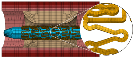
Figure 2. Finite element mesh for the whole balloon-stent-plaque-artery system (50% stenosis and asymmetric plaque with a ratio of 7:3)
All simulations were performed using Abaqus/Explicit solver with controlled time increments [13]. The time increment was on the order of 10-8 s throughout the analysis. The internal and kinetic energies have been monitored during the analyses, and the kinetic energy for whole the system was always less than 5% of the internal energy, which confirmed the validity of our quasi-static analyses. Also, Abaqus used enhanced hourglass control approach for the hyperelastic materials (i.e., artery and plaque), which provides resistance to hour glassing.
Outer diameter change was monitored at 5 even points in the middle ring of the stent. The overall expansion of the stent was then calculated as the mean of the values obtained at those 5 points. Diameter change at both ends of the stent was also monitored at 5 even points along the circumferential direction to calculate the dogboning effect from the following equation [19]:
(1)
where de and dm are the mean diameters for the ends and the middle ring of the stent, respectively, after balloon deflation. The recoiling effect was calibrated from the tracked mean diameter of the middle ring of the stent using the following equation:
(2)
where d0 and d1 are the mean diameters for the middle ring of the stent at the peak of inflating pressure and in the end of balloon deflation, respectively.
In the case of asymmetric plaque, the expansion of the artery and the dogboning were monitored separately at the top, middle and bottom locations of the lumen (corresponding to points A, B and C in the inset of Figure 6a), respectively, where the plaque has the maximum, medium and minimum thickness. The maximum principal stress contours were produced at the end of deployment for all cases. Stress values around the middle ring of the intima, media and adventitia layers of the artery were plotted to help understand any potential damage of the arterial wall caused by stenting. Mesh sensitivity study has also been carried out, and confirmed the convergence of the results, in terms of stent diameter change, recoiling effect and vessel stresses, for the mesh used in this work.
Validation of the modelling approach was carried out by comparing the simulated free expansion of the balloon and the stent (without artery) with the data published by the manufacturer [20]. In both cases, good agreements were obtained for the final stage of expansion (Figures 3a and b; no data available for the early and sustained stages of expansion), which confirmed the validity of the method used in this paper.
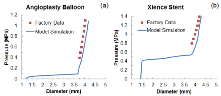
Figure 3. Comparison of diameter change against pressure between simulated results and factory data for free expansion of (a) the folded balloon and (b) the Xience stent
Results
Effect of plaque thickness
The change of stent’s outer diameter against the pressure is plotted in Figure 4a for Xience stent during the process of deployment inside a diseased artery with 40%, 50% and 60% stenosis. Overall, stent expansion at the maximum pressure (1.4 MPa) depended on the severity of stenosis, with diameter considerably reduced with the increasing plaque thickness. The artery with 40% stenosis achieved a diameter of 4.2 mm at the end of balloon inflation, and this diameter reduced to 4.1 mm for 50% stenosis and 3.7 mm for 60%. This is because the increasing plaque thickness increased the radial stiffness of the system which limited the expansion considerably at maximum pressure. During deflation, recovered elastic deformation and radial pressure from the viscoelastic artery system lead to the recoil of the stent. The diameter of the stent-artery system at the end of deflation was 4.0 mm for 40% stenosis, 3.5 mm for 50% stenosis and only 2.8 mm for 60% stenosis, indicating that the increased stenosis also increased the recoiling effect significantly. Specifically, the recoiling (Figure 4b) increased from a value of only 4.5% for 40% stenosis, to 15.6% for 50% stenosis and 25.7% for 60% stenosis, causing a large decrease in the diameter after the deflation of the balloon. The dogboning effect also dramatically increased with the level of stenosis, with values of 5.6%, 22.2% and 51.2% for 40%, 50% and 60% stenosis, respectively.
The maximum principal stress levels on the artery and plaque are compared in Figure 5 for the three different cases. The maximum stress increased markedly with the level of stenosis, showing 1.3 MPa for 40% stenosis, 2.3 MPa for 50% stenosis and 2.9 MPa for 60% stenosis. In all three cases, the highest stress was located on the surface of the plaque. It should be noted that the model used for arterial tissues is isotropic and unable to catch the anisotropic behaviour of the vessel. Also the material model does not include plastic behaviour for the vessel which might affect the results by over-predicting stent recoil and vessel stress due to the stiffer stress-strain curve developed for the vessel wall and hard plaques at later stage (~20% strain) [5,16,17].
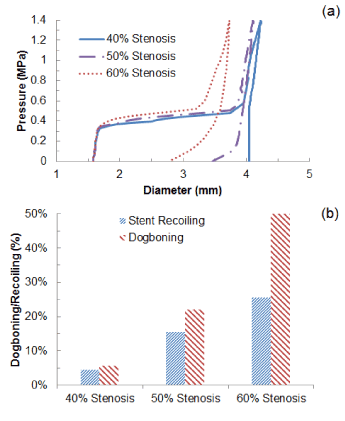
Figure 4. (a) Change of stent outer diameter against pressure and (b) recoiling and dogboning effects for stent deployment in arteries with 40%, 50% and 60% stenosis
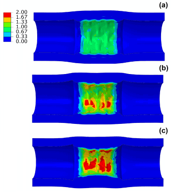
Figure 5. Contour plot of maximum principal stress (MPa) in the artery-plaque system after stent deployment in arteries with (a) 40%, (b) 50% and (c) 60% stenosis
Effect of plaque asymmetry
Figure 6a shows the change of diameter against the pressure for asymmetric plaque (ratio 7:3 and 9:1), in comparison with that for a symmetric plaque (ratio 1:1). The expansion of the system appeared to be non-uniform due to the varied thickness of plaque. For asymmetry ratio of 7:3, the lumen radius expanded from 1 mm to 1.58 mm at point A where the plaque was the thickest and to 1.74 mm at point C where the plaque was the thinnest. Plaque asymmetry also led to the development of non-uniform dogboning effect. The dogboning was around 20% when calculated at point A and reduced dramatically when calculated at point C, with only 6% for plaque asymmetry ratio 7:3 and 1% for plaque asymmetry ratio 9:1 (Figure 6b).
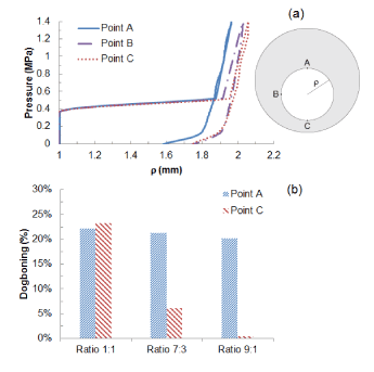
Figure 6. (a) Radial expansion against pressure at points A, B and C for asymmetric plaque (ratio 7:3); (b) Comparison of dogboning effects at points A and C for symmetric (1:1) and asymmetric (7:3 and 9:1) plaques.
Figure 7 shows the distribution of maximum principal stresses on the artery-plaque system. Increased stress levels were found on the plaque with the increase of asymmetric ratio. It is particularly noticed that there is a significant increase of stress levels in the intima and media layers in the healthier section of the artery, i.e., with thinner plaque. For the case with 9:1 asymmetric ratio, the stress magnitude reached a level above 1 MPa, which can be associated with the risk of arterial damage. To illustrate this more clearly, Figure 8 plots the stress variation around the circumferential direction for the middle section of the arterial layers. In the case of symmetric plaque, the stresses on the three layers were almost constant along the circumferential direction with a value of ~10 kPa in both the intima and media layers and ~5 kPa in the adventitia layer. In the case of asymmetric plaque, this value is slightly decreased for the section with thicker plaque (q > 180°), but significantly increased for the section with thinner plaque (q < 180°). The stress magnitude in the intima layer increased to 445 kPa for the case with plaque asymmetric ratio 7:3 and 1643 kPa for the case with plaque asymmetric ratio 9:1, indicating an extremely high risk of arterial damage. The same effect is also noted for the media and adventitia layers, with a magnitude of 212 kPa and 378 kPa in the media and 8 kPa and 18 kPa in adventitia for asymmetric plaque ratio 7:3 and 9:1, respectively. Figure 9 shows the stress distribution on the media and adventitia layers in the case of ratios 7:3 and 9:1. Results confirmed that the highest stress were located on the side of the artery which has thinner plaque. It can be noted that not only the stress magnitudes increase with the plaque asymmetry, but also stress concentration tends to occur in smaller areas of vessel layers with the increase of plaque eccentricity.
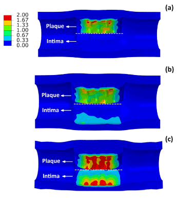
Figure 7. Contour plots of maximum principal stress (MPa) on the plaque and intima layer for (a) symmetric (ratio 1:1) and asymmetric (ratio (b) 7:3 and (c) 9:1) plaques
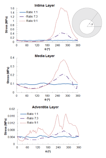
Figure 8. Circumferential variation of maximum principal stress (MPa) on the intima, media and adventitia layers for symmetric (ratio 1:1) and asymmetric (ratio 7:3 and 9:1) plaques
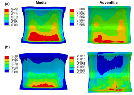
Figure 9. Contour plots of maximum principal stress (MPa) on the media and adventitia layers, in the case of plaque asymmetry ratios of (a) 7:3 and (b) 9:1.
Effect of artery curvature
Deployment of stent in artery, with 30° and 60° bends at the diseased location, was simulated and the results of expansion are shown in Figure 10, in comparison with that obtained for a straight artery. The final diameter after deflation (Figure 10a) was slightly reduced for a 60°-bend artery, with a value of 3.3 mm, compared to 3.5 mm for a straight artery. There is almost no difference for stent expansion in a 30°-bend artery when compared to that in a straight artery. The recoiling and dogboning effects are also very similar in all three cases, with recoiling around 15% and dogboning around 20%. We also noticed that the bended artery was generally straightened following stent deployment, as also reported in Auricchio et al. [21]. To quantify such straightening effect, Figure 10b compares the degree of tortuosity, calculated as the ratio between the distance of the two end points of the artery and the length of its centreline, before and after stent deployment. It is noted that, following stent deployment, arterial tortuosity reduced from 44.6% to 37.7% for 60°-bend artery and from 3.1% to 2.9% for 30°-bend artery. Figure 11 shows the stress contour plotted on the deformed shape of the artery for three cases. Clearly, the stress on the plaque increased with the increasing curvature of artery. The stresses on the straight artery were only 2.27 MPa, and increased to 3.22 MPa and 3.62 MPa for the 30° and 60° bend arteries, respectively. For curved artery, the highest stress was located at the inner and outer bends of the vessel.
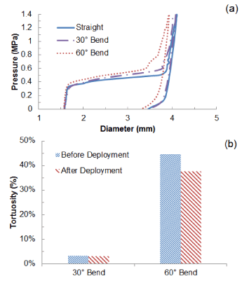
Figure 10. (a) Change of stent outer diameter against pressure for stent deployment in straight, 30o-bend and 60o-bend arteries; (b) Degree of artery tortuosity before and after stent deployment.
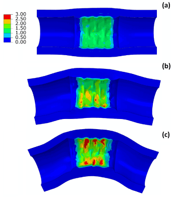
Figure 11. Contour plots of maximum principal stress (MPa) for (a) straight, (b) 30°-bend and (c) 60°-bend arteries
Discussion
Cheng et al. [22] analysed the stress distribution on plaques, showing that the circumferential stress plays a primary role on plaque rupture, along with the local variation in plaque properties. Stress analysis of plaques, subjected to internal pressure, has also been carried out by Li et al. [23] through a combination of MRI imaging technique and FE analysis. Their findings showed that stress distribution can be used to predict the location of plaque rupture, and plaques which underwent rupture experienced considerably higher stresses (0.68 MPa) compared to those not ruptured (0.23 MPa). Our results highlighted the importance of plaque thickness in stent deployment. For thick plaque, there is a risk of an unsuccessful treatment of the disease and also a potential of plaque rupture due to the high stress levels developed at a focalised area of the plaque. In our paper, the stresses in the artery-plaque system were found to be in the range of 1~3 MPa, depending on the severity of stenosis. It should be pointed out that the predicted maximum stresses on the plaque are beyond the ultimate tensile stress values for tissue layers as reported in Holzapfel et al. [16]. Consequently, damage behaviour needs to be incorporated in the Ogden hyperelastic model at such high stress levels, which might mitigate the stent recoiling upon balloon deflation due to the irreversible deformation associated with tissue damage. This requires a considerable amount of new work and will be considered in our future studies.
Clinical trials have demonstrated an association of stent angioplasty with the increase of artery perforation [24]. This can be caused by the guide wires, the angioplasty balloons or the stent itself, and is a life-threatening condition that can be classified into three types: Grade I extraluminar crater, Grade II, myocardial or pericardial blushing, and Grade III, contrast streaming or cavity spilling [24]. Studies of artery perforations in stent deployment showed that Grade I perforations are mainly caused by the angioplasty catheter, whilst angioplasty balloon and stents are connected mainly to Grade II and Grade III lesions [25,26]. According to our results, the stress concentration in the arterial layers of the artery can be considered as a risk factor for the perforation of the artery during stent deployment. This work suggests that the presence of the plaque reduces the stresses in the vessel walls, protecting the artery from the eventuality of perforation. When the plaque becomes too thin, the artery is more exposed to damage caused by the stent, and the doctor should be alerted when performing the surgery in patients with severe asymmetric plaques.
The deployment of stents in tortuous or curved arteries is one of the major clinical challenges, resulting often in failure of stent placement or damage to the artery. Fernandes et al. [27] reported three cases of stent angioplasty on angulated lesions, and found that arterial bends or sharp vessel angulation can obstruct the passage of the stent. Myouchin et al. [28] studied 31 cases of stent deployment close to inflection points of the artery, of which 2 had unsuccessful treatment of the lesion. Analysis of lesions showed that both unsuccessful cases were experiencing a vessel tortuosity close to 90° with the stenosis located in the middle of the arterial bend. From our results, the curvature of the artery affected the stent expansion only slightly, by reducing the gain in lumen diameter during the deployment. Also, the recoiling and dogboning effects were similar in all cases, suggesting that these effects are mainly associated with the severity and asymmetry of stenosis rather than the shape of the vessel.
In fact, Auricchio et al. [21] carried out the simulation of deployment of six stent designs inside a patient specific artery, digitally reconstructed by computed tomography angiography (CTA). Their results revealed that stent deployment significantly reduced the tortuosity of the artery, which is the case for all six designs. The stent design had no influence in vessel straightening, although it affected the stresses on the arterial wall and the lumen gain. Morlacchi et al. [29] produced two models of patient specific arterial bifurcation with CTA to simulate stent deployment. The study showed that tortuosity of the artery was reduced in both cases, resulting in a straightening of the vessel. Furthermore, high stresses, on both the stents and the arteries, can be found in the areas of vessel straightening and stent overlapping, leading to potential stent and arterial failure. These phenomena were also confirmed in our simulations of stent deployment in curved arteries, where artery straightening happened mostly at the inner and outer bends, leading to the development of high stress levels and a risk of plaque rupture at those regions.
Conclusions
Stent expansion and recoiling are strongly affected by the severity of stenosis. The radial stiffness of the diseased artery increased considerably with the increase of plaque thickness, which leads to reduced stent-artery expansion, high levels of stent recoiling and increased stresses on the plaque. For symmetric plaque, the stresses on the arterial walls were uniform and relatively low in magnitude due to the uniform expansion of the stent. For asymmetric plaque, the stent expansion becomes non-uniform, which is also the case for the dogboning effect. Stent expansion is very limited in the regions with thicker plaque, also accompanied by high dogboning effect. The stresses drastically increased in the regions with thinner plaque and were mainly located in the intima and media layers of the artery. A reduction in stent expansion and an increase for the stresses on the plaque were obtained when stent deployment was simulated in curved arteries.
This work highlights different situations, associated with the geometrical character of diseased blood vessels, for which stent deployment might represent a risk for arterial damage and plaque rupture. Results suggest that severe stenosis might require stent designs such as closed cell designs that are resistant to recoiling in order to treat the disease effectively. Still, particular care should be taken when implanting stents in plaques that are not evenly distributed around the artery, as non-uniform expansion and arterial damage might occur in the areas where the plaque is particularly thin. This also includes deploying a stent in arteries with sharp curvatures due to high stresses induced at the inner and outer bends.
References
- Riley RF, Don CW, Powell W, Maynard C, Dean LS (2011) Trends in Coronary Revascularization in the United States From 2001 to 2009 Recent Declines in Percutaneous Coronary Intervention Volumes. Circ Cardiovasc Qual Outcomesa, 4: 193-197. [Crossref]
- Moore JE, Soares JS2021 Copyright OAT. All rights reservtents: biomechanical modeling challenges and opportunities. Cardiovascular Engineering and Technology 1: 52-65.
- Chua SD, Mac Donald B, Hashmi M (2003) Finite element simulation of stent and balloon interaction," Journal of Materials Processing Technology 143: 591-597.
- Lally C, Dolan F, Prendergast PJ (2005) Cardiovascular stent design and vessel stresses: a finite element analysis. J Biomech 38: 1574-1581. [Crossref]
- Schiavone A, G Zhao L, Abdel-Wahab A (2014) Effects of Material, Coating, Design and Plaque Composition on Stent Deployment inside a Stenotic Artery-Finite Element Simulation. Mater Sci Eng C Mater Biol Appl 42: 479–488. [Crossref]
- Imani SM, Goudarzi A, Ghasemi S, Kalani A, Mahdinejad J (2014) Analysis of the stent expansion in a stenosed artery using finite element method: Application to stent versus stent study. Proc Inst Mech Eng H 228: 996-1004. [Crossref]
- Demir AG, Previtali B, Ge Q, Vedani M, Wu W, et al. (2013) Biodegradable magnesium coronary stents: material, design and fabrication. International Journal of Computer Integrated Manufacturing 27: 936-945.
- Clune R, Kelliher D, Robinson JC, Campbell JS (2014) NURBS modeling and structural shape optimization of cardiovascular stents. Structural and Multidisciplinary Optimization 50: 1-10.
- Morlacchi S, Pennati G, Petrini L, Dubini G, Migliavacca F (2014) Influence of plaque calcifications on coronary stent fracture: A numerical fatigue life analysis including cardiac wall movement. J Biomech 47: 899-907. [Crossref]
- Liu J, Jia XJ, Wang YJ, Zhang M, Zhang T, et al. (2014) Digital Subtraction Angiography Imaging Characteristics of Patients with Extra–Intracranial Atherosclerosis and Its Relationship to Stroke. Cell Biochem Biophys 69: 599-604. [Crossref]
- Wu W, Wang WQ, Yang DZ, Qi M (2007) Stent expansion in curved vessel and their interactions: a finite element analysis. J Biomech 40: 2580-2585. [Crossref]
- Gu L, Zhao S, Froemming SR, (2012) Arterial Wall Mechanics and Clinical Implications after Coronary Stenting: Comparisons of Three Stent Designs. International Journal of Applied Mechanics 4: 1250013-1250027.
- Abaqus, Version 6.13, Dassault systems, Vélizy-Villacoublay, France, 2013.
- Gervaso F, Capelli C, Petrini L, Lattanzio S, Di Virgilio L, et al. (2008) On the effects of different strategies in modelling balloon-expandable stenting by means of finite element method. J Biomech 41: 1206-1212. [Crossref]
- Yamagishi M, Terashima M, Awano K, Kijima M, Nakatani S, et al. (2000) Morphology of vulnerable coronary plaque: insights from follow-up of patients examined by intravascular ultrasound before an acute coronary syndrome. J Am Coll Cardiol 35: 106-111. [Crossref]
- Holzapfel G, Gasser T, Ogden R, Ehlers W, Markert B (2004) Comparison of a structural model with a Fung-type model using a carotid artery: issues of material stability. J Biomech Eng 14: 79-89. [Crossref]
- Zahedmanesh H, Lally C (2009) Determination of the influence of stent strut thickness using the finite element method: implications for vascular injury and in-stent restenosis. Med Biol Eng Comput 47: 385-393. [Crossref]
- Ju F, Xia Z, Sasaki K (2008) On the finite element modelling of balloon-expandable stents. J Mech Behav Biomed Mater 1: 86-95. [Crossref]
- Migliavacca F, Petrini L, Colombo M, Auricchio F, Pietrabissa R (2002) Mechanical behavior of coronary stents investigated through the finite element method. J Biomech 35: 803-811. [Crossref]
- Abbott Vascular XIENCE Xpedition™, XIENCE Xpedition SV and XIENCE Xpedition LL everolimus eluting coronary stent systems instructions for use 2012.
- Auricchio F, Conti M, De Beule M, De Santis G, Verhegghe, B (2011) Carotid artery stenting simulation: From patient-specific images to finite element analysis. Med Eng Phys 33: 281-289. [Crossref]
- Cheng GC, Loree HM, Kamm RD, Fishbein MC, Lee RT (1993) Distribution of circumferential stress in ruptured and stable atherosclerotic lesions. A structural analysis with histopathological correlation. Circulation 87: 1179-1187. [Crossref]
- Li ZY, Howarth S, Trivedi RA, U-King-Im JM, Graves MJ, et al. (2006) Stress analysis of carotid plaque rupture based on in vivo high resolution MRI. J Biomech 39: 2611-2622. [Crossref]
- Al-Mukhaini M, Panduranga P, Sulaiman K, Riyami AA, Deeb M, et al. (2011) Coronary perforation and covered stents: an update and review. Heart Views 12: 63-70. [Crossref]
- Javaid A, Buch AN, Satler LF, Kent KM, Suddath WO, et al. (2006) Management and outcomes of coronary artery perforation during percutaneous coronary intervention. Am J Cardiol 98: 911-914. [Crossref]
- Yildiz A, Karakurt A, Bitigen A, Bagirtan B (2013) Fatal complication, rescue therapy; covered stent for coronary artery perforation. Health 5: 1-5.
- Fernandes V, Kaluza LG, Godlewski B, Li G, Raizner EA (2002) Novel Technique for Stent Delivery in Tortuous Coronary Arteries: Report of Three Cases. Catheter Cardiovasc Interv 55: 485-490. [Crossref]
- Myouchin K, Takayama K, Taoka T, Nakagawa H, Wada T, et al. (2013) Carotid Wallstent placement difficulties encountered in carotid artery stenting. Springerplus 2: 468-474. [Crossref]
- Morlacchi S, Colleoni SG, Cárdenes R, Chiastra C, Diez JL, et al. (2013) Patient-specific simulations of stenting procedures in coronary bifurcations: two clinical cases. Med Eng Phys 35: 1272-1281. [Crossref]


