Post-ablation reoccurrence of atrial fibrillation (AF) presents a continuing concern in the treatment of such patients; ablation of the mitral isthmus (MI) is routinely conducted to decrease the likelihood of macro-reentrant tachycardias. However, creation of transmural MI blocks for treatment of AF is difficult to achieve as catheter placement, stability, and tissue contact are challenging due to unique patient anatomy. We employed Visible Heart® methodologieswithin a reanimated human heart (considered nonviable for transplantation) during placement of a catheter against the MI to observe the device-tissue interface. This unique in vitro imaging aided in a better understanding of the challenges of catheter navigation related to cathetermovement, placement, orientation, and stability within the left atrium during MI ablation procedures. This direct visualization approach was also useful to explore additional variables such as catheter tip angle, power delivery, and ablation duration as a means to modify clinical approaches for improved linear lesion generation.
In this report we employed direct imaging modalities within a reanimated human heart during the placement of a catheter against the MI as a means to provide novel educational tools for physicians, design engineers, and/or patients, i.e., to better understand the specific limitations of the current procedure and suggest procedural changes that can lead to improve linear lesion generation.
Case report
A human heart was reanimated in a clear Krebs-Henseleit buffer using Visible Heart® methodologies,and endoscopic footage during an ablation procedure was obtained [11,12]. This heart was considered nonviable for transplantation (recovered via LifeSource, St. Paul, MN, USA). We also used a reanimated swine heart to validate this ablative approach using post-procedure tissue dissection and staining; this heart was recovered after an unrelated experiment. The catheters were advanced through the inferior vena cava, across the fossa ovalis (FO), to the anatomical location of the left atrial MI. A 4 mm Marinrradio frequency catheter (Medtronic, Inc., Minneapolis, MN, USA) was advanced through a transseptal sheath to the desired position against the MI. The catheter ablation was setto 50 W and the creation of the linear lesion occurred over a 17-minute period.
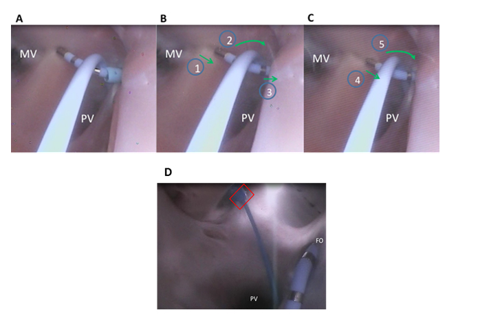
Shown in Figure 1A, the catheter tip was placed next to the annulus of the mitral valve (MV). A second diagnostic catheter was inserted through a separate sheath (Figure 1D). It wasplaced such that the interior of the deflection point of the ablation catheter rested on the shaft of the diagnostic catheter. The tip of the diagnostic catheter was logged in the pulmonary vein (PV) to anchor the diagnostic catheter and restrict movement of the ablation catheter. The ablation energy was turned on and a lesion was created as the catheter was dragged toward the ostium of the PVs, which are located in the center of the screen below the ablation catheter shaft (Figure 1A). As the ablation catheter was pulled along the ridge, the ablated tissue appeared to become dimpled and it changed in color (Figure 1B).
Figure 1. A mitral isthmus (MI) linear lesion created in a reanimated human heart: (A) initiation of the linear lesion with support from a transseptal sheath and secondary diagnostic catheter; (B) the ablation catheter (1) is pulled along the MI with twisting of a diagnostic catheter (2) towards the fossa ovalis, and retraction of the transseptal sheath (3) from the left atrium; (C) increased deflection of the ablation catheter (4) and increased twisting of the diagnostic catheter (5); both the transseptal sheath and a support catheter were advantageous to maintain contact on the MI; (D) diagnostic catheter is introduced through a second delivery sheath that is inserted through a cannulated pulmonary vein (PV) into the left atrium (red box). FO=fossa ovalis; MV=mitral valve
The catheter was then advanced over a ridge in the left atrium. To generate good contact, abundant deflection of the ablation catheter tip was required and the delivery sheath was also utilized for added support (SupplementalVideo A). Yet, during the course of the ablation, the delivery sheath was retracted into the right atrium to better allow for the ablation catheter tip to maintain contact as it was pulled across the MI (Figure 1C). Persistent contact between the ablation catheter and diagnostic catheter were required in order to maintain tip orientation and prevent the ablation tip from sliding along the tissue (Figure 1B). Finally, the support of the diagnostic catheter prevented the ablation catheter from changing orientation to its side. During the course of visualizing such ablation procedures, we observed that there wasa procedural need for a high number of deflections of the ablation catheter. In some cases a MI ablation required a 90-120 degree deflection of the delivery sheath at its distal tip, to achieve placement of the ablation catheter in the desired location (Supplemental VideoA).
Supplemental Video A: Linear lesion creation of the mitral isthmus using an alternative approach, as viewed from the pulmonary vein.
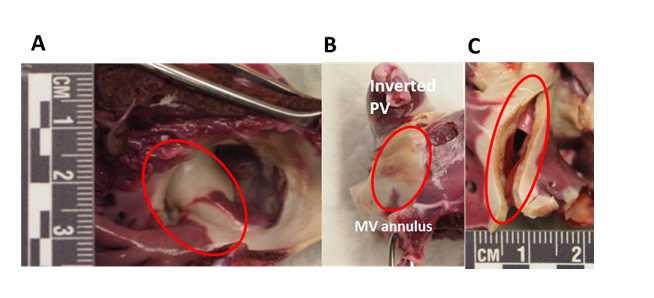
Upon completion of the human heart ablation, this procedure was validated in a swine model to examine the effectiveness of the technique using a post-procedure lesion assessment. Swine post-procedural evaluations included the use of triphenyl tetrazolium chloride (TTC). Each sample was placed in a TTC bath for 20 minutes to allow for the creation of color differentiation and the ability to visualize healthy versus dead tissue; ablated tissue appeared blanched and non-ablated tissue was deep purple (Figure 2).
Figure 2. Several views of sectioned and TTC-stained left atrial samples. (A) The ablated atrial tissue appears blanched; (B) the pulmonary vein (PV) is inverted and the mitral valve (MV) line is circled; (C) cross-sectional view of linear mitral isthmus lesion, depicting transmurality.
Via the staining, the presence of the ablated region became quite visible (Figure 2A). The pulmonary vein and atrial tissue were then inverted to further examine the full extent of the linear lesion which extended form the MV annulus to the PV ostium (Figure 2B). Finally, the lesion was sliced to examine lesion transmurality (Figure 2C). These results show that the ability to generate a successful lesion in this MI anatomy is influenced by maintaining tip orientation and high tissue contact. In this case, these were influenced by the support of a delivery sheath that was retracted into the right atrium during the ablation, and a secondary support catheter was also used to provide support to the ablation catheter (Figure 3A, B).
Discussion
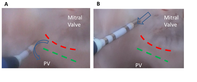
The clinical approach shown here isan innovative way to utilize currently available ablation tools as a means to increase the success rate of achieving a transmural lesion of the MI. Studies show that conduction block at the MI can be challenging, furtherreinforcing the need for advanced ways to treat such patients [13]. The presence of the ridge that may border between the MV annulus and the PV can be a verychallenging anatomy, due toits various shapes and sizes. As the catheter tip is moved over the ridge, the tip can lose contact, making it difficult to ablate all the tissue on both sides of the ridge (Figure 3A). In addition, the orientation of the sheath and the proximity of the MV annulus can result in the catheter ablation electrode laying on its side against the tissue (Figure 3B). This orientation limits the amount of force that can be placed on the tissue by the ablation catheter, as the catheter will slide along the tissue as more contact force is placed against it.
Figure 3. Movement of the catheter using a traditional approach. (A) Catheter tip movement (blue arrow) over the ridge (green dash); (B) catheter tip drag (blue arrow) starting a mitral isthmus ablation in the direction of the ridge (green dash). PV=pulmonary vein
This is considered to contribute to an inability to maintain tissue contact that is sufficient to generate transmural lesions (Supplemental Video B). In addition, the relative location of the MI relative to the fossa ovalis prevents the delivery of a long section of steerable sheaths and/orcatheters into the left atrium, i.e., often reducing the relative amount of contact the catheter shaft can have on the MI. It has been noted that innovative approaches are often needed that allow for better forces to be transferredfrom the ablation catheter tip along endocardial tissue. Suchcapabilities would,in turn,allow for greater contact forcesand result in more consistent transmurallesions. This study utilized Visible Heart® methodologies as a novel means to observe the device-tissue interface during the combined approach of catheters and sheaths to augmentablation outcomes. These insights may help clinicians in their desire to enhance clinical outcomes for transmural MI lesion generation.
Supplemental Video B: Linear lesion creation of the mitral isthmus using a traditional catheter approach, as viewed from the pulmonary vein.
Conclusions
The unique in vitro imaging of reanimated hearts employed here aided in a better understanding of the challenges of catheter navigation related to movement, placement, orientation, and stability within the left atrium during MI ablation procedures. This direct visualization approachwas useful to explore additional variables such as catheter tip angle, power delivery, and ablation duration as a means to modify clinical approaches to achieve appropriate catheter placements for ultimately eliciting proper lesion formations.
Funding source
This study was funded by a research contract with Medtronic, Inc.
Benscoter MA, Avitall B, Iaizzo PA (2015) Visualization of an innovative approach for mitral isthmus ablation. J Integr Cardiol, 1: DOI: 10.15761/JIC.1000139
Corresponding author
Paul A. Iaizzo
Professor, Department of Surgery, University of Minnesota, 420 Delaware Street S.E., B172 Mayo, MMC 195, Minneapolis, MN 55455, USA; Tel: (612) 624-7912; Fax: (612) 624-2002.
Supplemental Video A: Linear lesion creation of the mitral isthmus using an alternative approach, as viewed from the pulmonary vein.
Supplemental Video B: Linear lesion creation of the mitral isthmus using a traditional catheter approach, as viewed from the pulmonary vein.
Figure 1. A mitral isthmus (MI) linear lesion created in a reanimated human heart: (A) initiation of the linear lesion with support from a transseptal sheath and secondary diagnostic catheter; (B) the ablation catheter (1) is pulled along the MI with twisting of a diagnostic catheter (2) towards the fossa ovalis, and retraction of the transseptal sheath (3) from the left atrium; (C) increased deflection of the ablation catheter (4) and increased twisting of the diagnostic catheter (5); both the transseptal sheath and a support catheter were advantageous to maintain contact on the MI; (D) diagnostic catheter is introduced through a second delivery sheath that is inserted through a cannulated pulmonary vein (PV) into the left atrium (red box). FO=fossa ovalis; MV=mitral valve
Figure 2. Several views of sectioned and TTC-stained left atrial samples. (A) The ablated atrial tissue appears blanched; (B) the pulmonary vein (PV) is inverted and the mitral valve (MV) line is circled; (C) cross-sectional view of linear mitral isthmus lesion, depicting transmurality.
Figure 3. Movement of the catheter using a traditional approach. (A) Catheter tip movement (blue arrow) over the ridge (green dash); (B) catheter tip drag (blue arrow) starting a mitral isthmus ablation in the direction of the ridge (green dash). PV=pulmonary vein