Objective: To develop and apply a novel diagnostic graphical model for analyzing frontal cephalometric radiographs to determine the exact location of a maxillofacial asymmetry.
Material and methods: Standard frontal cephalometric radiographs of 64 patients with visible craniomandibular asymmetry were taken. Known cephalometric points were used and the midsagittal line was built using the Sassouni method. The evaluation of the grade of severity of the facial asymmetry is based on the research of Buranostidporn et al. To identify the exact location of the maxillofacial asymmetry, more bilateral points than the ones known from the literature are required. In order to determine the symmetry of a facial contour where there are no known bilateral points, we elaborated our own independent graphic model-the Concentric Arcs Method.
Results: The analysis of our sample of patients with our own independent Concentric Arcs Method found that 51.5% of them have both mandibular and maxillary asymmetry, whereas 48.5% of the patients have only mandibular asymmetry. We evaluated the grade of severity of the facial asymmetry. We establish the distribution of the studied 64 patients, depending on the three degrees of facial asymmetry.
Conclusion: The created graphic method and applied on frontal cephalometric radiographs estimates the exact location of facial asymmetry, facilitates determining whether the reason for these discrepancies is to be found in the maxilla and/or the mandible, and offers a basis for setting limit values of the severity degree of transverse maxillofacial discrepancies.
frontal teleradiographs, cephalometry, facial asymmetry, mandibular asymmetry
Orthodontic patients with dentoalveolar and facial asymmetry as well as dental and skeletal crossbite in the lateral segment of the dentition, and functional mandibular displacement need a detailed three-dimensional diagnostic examination [1]. We know that faces are various and specific in size and a little anomaly in one could be a rather serious problem in others. The questions that concern the orthodontist are: ‘Where is the problem?’, ‘What is the problem?’, ‘How severe is the problem?’, ‘How can the patient be helped, and the problem treated successfully?’. Frontal cephalometric radiography provides useful information for answering these questions, yet it is rarely used by orthodontists due to the difficulties in specifying cephalometric landmarks [2]. If the orthodontist does not analyse and pinpoint the problem and create a thorough and proper treatment plan based on this analysis, this could lead to a symptomatic treatment with improper, unsatisfactory results and relapse.
All frontal cephalometric methods known in the literature complement each other to a certain extent and help to elaborate an objective paraclinical diagnosis of transverse jaw problems and facial asymmetry. The methods for diagnosing these discrepancies which can be used to point the exact location and specify the starting point of a facial asymmetry are very few. Whether it is in the maxilla and/or the mandible, from which points of the respective segments of the maxilla and/or mandible it starts and where it ends are questions directly concerning clinicians and crucial for elaboration of the correct treatment plan.
Objective
We set out to develop and apply our own diagnostic graphic model for analysing frontal cephalometric radiographs to determine the exact location of the starting and/or end points of a facial asymmetry.
Frontal cephalometric radiography provides valuable information for the exact and proper diagnosis of this type of discrepancies.
Standard frontal cephalometric radiographs of 64 patients with visible craniomandibular asymmetry were taken. All of them had voluntarily sought counselling and had been admitted for treatment at the Department of Orthodontics at the Faculty of Dental Medicine in Plovdiv. They were informed about the nature and purpose of the study. They signed a Declaration of informed consent for participation and Form of information about the patient, the risks and expected benefits of the study.
Certain bilateral landmarks (cephalometric landmarks on one side of the facial structures, which have their analogical symmetric projections on the other side) are used for analyzing the radiographs. These are described in detail by several authors [1-6].
For the elaboration of our graphic model, only some of these landmarks were used: p. Lo-latero-orbitalae (left and right)-the intersection point of the lateral orbital contour and the greater wing of the sphenoid bone; p. Nc-the base of Crista galli; p. Me (menton)-the lowest point of the mandibular symphysis; p. Co – condylion (left and right)=the highest point of the condyle; p. Ag-antegonion (left and right)-the most inferior margin of the antegonial protuberance before angulus mandibulae; p.ANS-spina nasalis anterior (Figure 1).
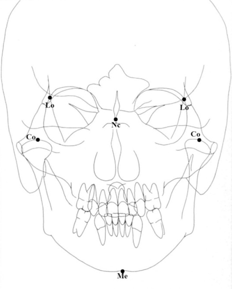
Figure 1. Cephalometric landmarks
We built the midsagittal reference line (MSR) of the facial structures using the Sassouni method from p. Nc a perpendicular ran to the straight line connecting the left p. Lo to the right one (Figure 2) [5-8].
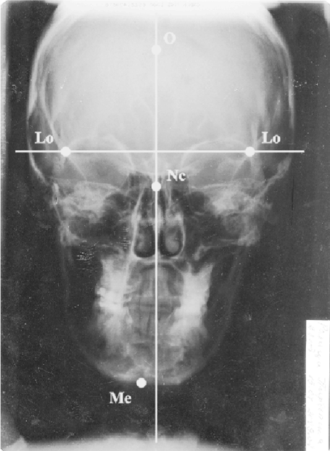
Figure 2. Building midsagittal reference line of a face using Sassouni method
We chose this method for building the facial midsagittal reference line because, according to Pearson et al. [9], the sphenoid bone shows exceptional symmetry. According to Keith et al. [10], p.Lo is a very good reference point for comparing growth and development of the skull. Scott et al. [11], found that the upper outer (lateral) orbital (left and right) contour is a stable reference zone after the age of 8. Regarding p.Сg, Letzer et al. [12], have pinpointed it in the mid-sagittal plane.
The Ag- Ag points are connected. This is the so-called frontal mandibular plane (FMP) in frontal cephalometry. We used the research of Buranostidporn et al. [13]. They measured the angle formed by FMP (the Ag–Ag line) and the perpendicular bisector drawn to MSR (Figure 3). Based on their studies the authors have determined three degrees of severity of facial asymmetry. When the inclination of the FMP is: FMP< 4° there is slight asymmetry; FMP = 4-7° -moderate asymmetry; FMP > 7°- severe asymmetry [14].
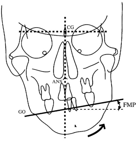
Figure 3. Measuring the inclination of FMP [13].
Statistical processing of the results was performed using the Statistical Package IBM SPSS, Version 24.0.0. The use of computing devices hugely facilitates the work on determining the cephalometric landmarks and graph drawing. Any drawing software can be used. For data processing and computing we recommend using Microsoft products-word/Excel. For the purposes of our diagnostics, we developed a specialized software in Bulgarian language called OrthoMup [15]. Measurements (angular and linear) are automatically performed by the applied software. Thus, measurement errors are eliminated and identifying cephalometric landmarks is facilitated, which makes facial cephalometric radiographs easier to read and more often preferred for diagnosing transverse facial discrepancies.
In cases of moderate or severe facial asymmetry, the starting point of the transverse problem must be located (in the maxilla and/or mandible). For this purpose, considerably more bilateral landmarks than the known ones must be used, but their number is limited in the areas we are interested in. The question arises: How could one determine the symmetry of a certain facial contour without any known bilateral points there? The solution is given by the graphic model elaborated by us.
The concentric arcs method
In order to determine whether two given contours are symmetric to one straight line, it must be determined which points of one contour correspond to which points of the other contour. For this purpose, we used the rule that matching points must be at equal distance from a given straight line (perpendicular bisector) and lie on a circumference with a center point p. О on the straight line. We drew the facial midsagittal reference line (MSR) using the Sassouni method. Different concentric arcs were drawn with a random center p. О lying on the midsagittal reference line (MSR), in its most upper part. For a more comprehensive picture, these arcs were drawn in shorter intervals, for instance 3-4 mm (Figure 4 and 5). The pairs of matching points on the left and right (A1, B1; A2, B2, etc.; C1, D1; C2, D2, etc.) were determined-intersecting points of the skull contours with the respective arcs (Figure 6).
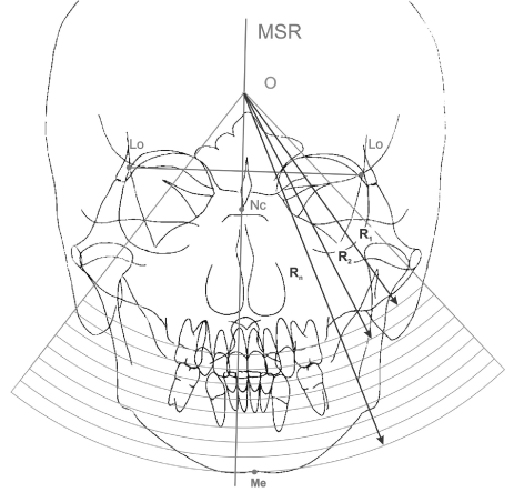
Figure 4. Drawing of concentric arcs.
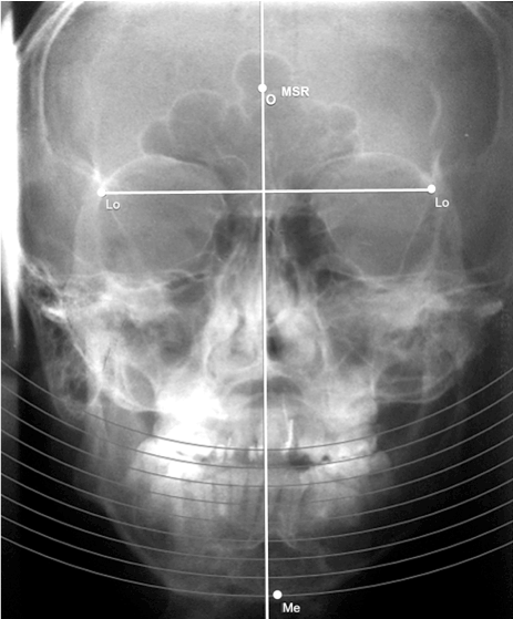
Figure 5. Computer drawing of concentric arcs
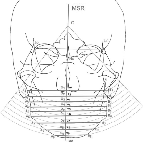
Figure 6. Pairs of matching points
By connecting the pairs of matching points, we obtained straight lines forming angles (α1, α2, α3, etc.) with the midsagittal line. The first obtained angle α ≠ 90° indicated the presence of asymmetry growing as much as the α angle deviated above or below 90° (Figure 7). This angle represents the vertical component of facial asymmetry. In addition, linear distances from the left and right bilateral points to the midsagittal line can be measured, which is the horizontal component of asymmetry. Thus, both characteristics of the maxillofacial asymmetry are considered simultaneously.
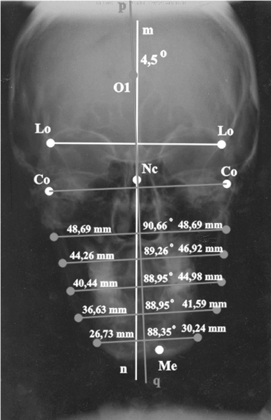
Figure 7. Computer measurement of angle α and distances on both sides of the midsagittal line
Visual assessment of facial asymmetry is very subjective. The reason for this is most often in the mandible. In practice, we often determine the symmetry of the mandible according to the midsagittal line of the skull. This can fool us. For example, the mandible may be symmetrical, but if it is rotated in the joints, the chin is displaced from the facial midsagittal reference line and this will mislead us that the mandible is asymmetric. Therefore, we regarded the mandible as a separate body with its own symmetry axis. To draw it, we connected the two Co points (left and right) and drew a perpendicular line pq through the middle (point O1) of this line (Figure 8).
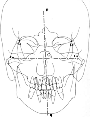
Figure 8. Drawing the symmetry axis of the mandible (pq)
If the point Ме is displaced to the left or to the right of the symmetry axis pq, this indicates that the mandible is asymmetric. To determine where the asymmetry of the mandible begins, we selected a random point lying as high as possible on the symmetry axis of the mandible and drew concentric arcs from it (Figure 9)
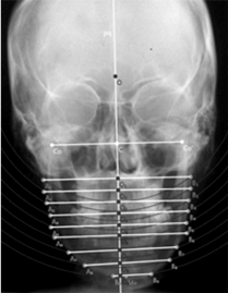
Figure 9. Using the Concentric Arcs Method to determine the beginning and the end of asymmetry of the mandible
In our study offacial cephalometric radiographs of64 patient with craniomandibular asymmetry, a great diversity of the location of asymmetry was found. The deviations of <α≠90° in each of the patients began at different locations in the middle and lower face. Cases have been observed where, after an initial <α> 90°, subsequent concentric arcs show <α < 90°, i.e., “S” deviation pattern (Figure 10).
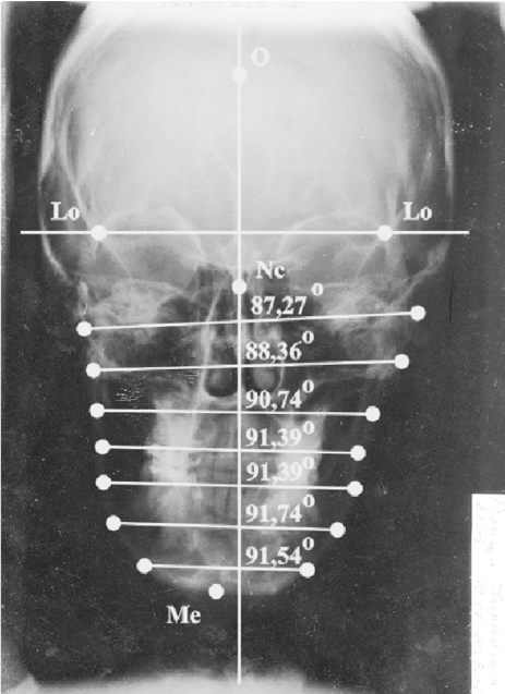
Figure 10. “S” deviation pattern result
In our study, we started measuring angles α1, α2, etc. from the mandible up to the skull base. For this reason, we assumed that the deviation which is nearest to p. Ме is the starting angle α≠90°. The last deviation of angle α≠90° is situated in the upper segment of the facial skeleton. Due to the strict individuality of the onset of deformity of the facial bone structures of each of the studied patients, their distribution in statistical groups proved impossible. Each person is a separate specific case. The frontal cephalometric radiographs of 33 (51.5%) of our patients showed asymmetry of both the mandible and maxilla at the same time. 31 patients (48.5%) had asymmetry of the mandible only. The severity of the deviations can be assessed based on the values established by Buranostidporn et al. [13,14]. Similarly, the following applies to our graphical method:
- At 90° - α < 4° – mild degree of deviation,
- At 90° - α = 4-7° – moderate degree of deviation,
- At 90° - α > 7° – severe degree of deviation.
Table 1 shows the distribution of the 64 patients with craniomandibular asymmetry and transverse occlusal discrepancies based on the three degrees of facial asymmetry.
Table 1. Distribution of patients based on the severity of the discrepancy
In some cases, the problem might not be in the mandible, but in the maxilla. Unilateral under development of the transverse and vertical growth of the maxilla (for example in cases of posterior crossbite) leads to mandibular displacement and occlusal plane discrepancy [16,17]. To determine the exact location and the nature of the transverse problem in facial bone structures, we developed our own graphic model.
The concentric arcs method
For greater precision in determining the location of the problem, we could make these arcs denser, i.е. decrease the differences of the radii more and more. Then the center of the concentric arcs must be situated in the uppermost part of the midsagittal reference line. This also applies for patients with relatively wider faces. If the center has been chosen on the lower part of the midsagittal reference line, then a smaller number of concentric arcs may intersect the facial contour. In such case, the pairs of matching points obtained through the intersection of these arcs with the facial contour will be situated in the lowest segment of the facial skeleton. But that can in no way change the method and its precision. For greater precision of the diagnosis, it is recommended to choose the center of the concentric arcs in the uppermost part of the midsagittal reference line and draw the arcs in smaller intervals. Drawing of the arcs and analysis by means of the software product OrthoMup is very precise.
The choice of intersection points of the concentric arcs on the respective facial contours depends on the part in which the orthodontist determines the necessary pairs of matching points. To avoid errors, the facial cephalometric radiograph must have good contrast and good quality. The occurrence of an additional subjective error is very unlikely and is related to the orthodontist’s experience in defining the necessary cephalometric landmarks.
For our method, it is of greater interest where the starting point of the facial deviation is – in the maxilla and/or the mandible – which will guide the orthodontist to choose the right treatment plan. The severity and location of the skeletal asymmetry dictate whether the discrepancy can be completely or partially resolved merely through orthodontic treatment. Severe facial discrepancies require combined surgical and orthodontic treatment. The Concentric Arcs Method developed by us will facilitate a more thorough diagnostics in order to determine if the maxilla and/or mandible need surgical repositioning. The orthodontist and the maxillofacial surgeon must join their efforts to obtain good and stable results.
The suggested herein independent graphic Concentric Arcs Method applied on frontal cephalometric radiographs determines the exact location of transverse skeletal discrepancies and facial asymmetry. Information obtained by means of this graphic model helps to determine whether the reason for the discrepancy is in the maxilla and/or the mandible. By means of the Concentric Arcs Method the vertical and horizontal components can be established at the same time and the degree of severity of facial skeletal deviations can be ascertained.
- Athanasiou E (1995) Orthodontic cephalometry, Mosby-Wolfe, England. p141-160.
- Miyashita K (1996) Contemporary cephalometric Radiography. Quintessense Publishing Co, Inc. Tokyo, Japan. p12-15; 168-209; 260-262; 288-290.
- Jondeph DR (2003) Diagnosis and Treatment of asymmetries. Annual Session, Vancouver, Canada.
- Langlade M (1981) Diagnostic Orthodontique. Editions Maloine, France. p23;24;55;77-91; 207-218.
- Muller L (1983) Cephalometrie et orthodontie. SNPMD, Editeur, Paris, p31-34;55-9;67-8;167-181;209-215.
- Sassounni V (1958) Diagnosis and treatment planning via roentgenographic Cephalometry. Am J Orthod 44: 433-463.
- Sassounni V (1970) Cephalometric trimming of dentalcasts. J.C.O. pp: 148-155.
- Thomas H, Chatenay Cl (1978) Chirurgie maxillofaciale et orthodontie. Masson, Paris, New York, Barselone, Milan, pp: 39-41.
- Pearson K, Woo TL (1935) Further investigation of the morphometric characters of the individual bones of the human skull. Biometrika 2: 423-465.
- Keith A, Campion GG (1922) A contribution to the mechanism of growth of the human face. Internat J Orthod 8: 607-633.
- Skott JH (1957) Growth in width of the facial sutures. Am J Orthod 43: 336-371.
- Letzer G, Kronman J (1967) A posteroanterior cephalometric evaluation of craniofacial asymmetry. Angle Orthod 37: 205-211. [Crossref]
- Buranastidrporn B, Hisanoand M, Soma K (2004) Articular disc displacement in mandibular asymmetry patients. J Med Dent Sci 51: 75-81. [Crossref]
- Buranastidrporn B, Hisanoand M, Soma K (2006) Temporomandibular joint internal derangement in mandibular asymmetry. What is the relationship? Eur J Orthod 28: 83-88. [Crossref]
- Boeva T (2017) Computer modeling of transverse facial discrepancies applied in orthodontic practice. Medical University-Plovdiv, Bulgaria.
- Bishara SE, Burkey PS, Kharouf JG (1994) Dental and facial asymmetries: a review. Angle Orthodontist 2: 89-98. [Crossref]
- Bishara SE (2001) Textbook of orthodontics, W.B. Saunders, Co. pp: 109-111;532-544.


