Abstract
Hydrogen has been largely exploited as an energy carrier particularly in fuel cells during recent years. Fuel cells are basically facilitate the capture of hydrogen and converting hydrogen power into useful energy. Interestingly, fuel cells have found their way into wider range of applications, such as backup power, power for remote locations, distributed power generation, and cogeneration of electricity. In this regard, it is highly expected that hydrogen can play a significant role in the near future to offer a clean, low cost, and eco-friendly alternative to fossil fuels. Herein, we will focus on the significance of hydrogen in various types of fuel cells as well as the working principle. Also, the advantages and disadvantages of these fuel cells will be highlighted.
Key words
fuel cell, alkaline fuel cell, sulfuric and phosphoric acid fuel cells, proton exchange membrane fuel cell, molten carbonate fuel cell, solid oxide fuel cells
Introduction
Hydrogen as an energy carrier has shown a very significant contribution to the advancement of fuel cells because it takes a great deal of energy to extract it from water. Hydrogen is considered as a secondary source of energy, commonly referred to as an energy carrier. Energy carriers are used to move, store and deliver energy in a form that can be easily used. Many companies are working hard to develop technologies that can efficiently exploit the potential of hydrogen energy.
A fuel cell is an electrochemical cell which alters the chemical energy from a fuel into electricity through an electrochemical reaction of hydrogen-containing fuel with oxygen or another oxidizing agent [1]. Fuel cells nowadays represent state of the art technology as a source of heat and electricity as an electrical power source for electric motors propelling vehicles. Fuel cells are electrochemical engines that generate electricity from redox reactions. One can think of them as batteries with flows of reactants in and products out. In contrast, the battery has a fixed supply of reactants that transform into products without being steadily replaced [2-8].
Fuel cells working principle
A fuel cell involves of an electrolyte film, inserted between two catalyst films. Numerous materials have been exploited in this concern. When a hydrogen atom contacts the negative anode catalyst layer, it splits into a proton and an electron. The proton passes through the central electrolyte layer, while the electron generates electricity as it passes through an external circuit. The circuit pushes the electrons to the positive portion of the electrolyte film; consequently, they bound with the proton and join an oxygen molecule, generating water in the positive cathode catalyst film.
The fuel cell itself can be slightly correlated to the alternator in a wind, hydro or engine generator. The fuel cell itself is the mechanism that actually produces the electricity. However, to produce electricity, the propeller or engine must turn the alternator. In order for a fuel cell to produce power, something must supply it with hydrogen and oxygen.
Numerous techniques have been employed to supply the fuel cell with the essential hydrogen and oxygen. Some systems use a "fuel reformer" to extract hydrogen from another fuel source such as propane, and can extract oxygen from the surrounding air. Some systems (in laboratory or industrial settings) are designed to be attached to tanks of pure hydrogen and oxygen. The basic principle of the fuel cell is depicted in the Figure 1.
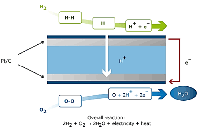
Figure 1. Principle of Fuel Cell.
The most fascinating technique of obtaining hydrogen, from a renewable energy viewpoint, is to use "electrolysis" to split water into hydrogen and oxygen, which is afterwards kept in tanks and fed into either end of the fuel cell. The "waste" water produced at the end of the fuel cell process is then fed back into the initial water source. A fuel cell generator set up to electrolyze and re-use water is known as a regenerative fuel cell. Any type of fuel cell could be used in a regenerative system, and the water electrolysis could be powered with wind, solar or hydro energy, resulting in a truly clean power system.
Fuel cells can power almost any portable devices that normally use batteries. Fuel cells can also power transportation such as vehiclesm as well as provide supplementary power to traditional transportations.
Types of fuel cells
Alkaline fuel cell
Sometimes called hydrogen-oxygen fuel cell was initially designed and first introduced widely by Francis Thomas Bacon in 1959. It was used as a main source of electrical energy in the Apollo space program [9]. Low temperature aqueous alkaline electrolyte cells have the advantage of being able to start up easily from cold, and operate usually at 60-80°C and provides a potential of about 0.9V [10], where the water vapor pressure of the electrolyte is appropriately high for a controlled removal rate. At these temperatures, highly active catalysts are required, usually of the platinum family. Silver and high-surface nickel has been used, however, as catalysts in this system; nickel is conventionally used as a conducting structural material.
Cheaper catalysts normally require higher operating temperatures; the Bacon cell is an example of a nickel catalyst used at 200-250°C. At these temperatures, either a high pressure must be applied to the system or highly concentrated solutions must be used to prevent water loss. High-pressure systems are not suitable for air operation, due to the high pumping energy required, whereas high concentration may cause corrosion, which restricts the choice of construction materials.
The intolerance of this type of cell to carbon dioxide is a major problem; it restricts the choice of fuel to pure hydrogen of hydrazine, and requires that the air filter removes 0.04% of the CO2 present in the air. The internal reforming cell is an attempt to get rid of this problem: the fuel electrode is made of palladium plus silver, and the fuel is either alcohol or a hydrocarbon which is reformed with steam on a nickel catalyst on one side of the electrode. The hydrogen formed passes through the electrode and reacts with the electrolyte, but the palladium prevents the CO2 to passes through and get into the electrolyte (Figure 2).
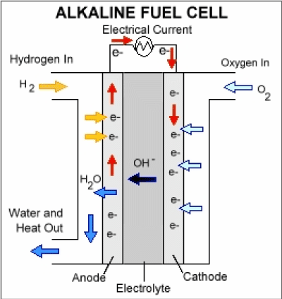
Figure 2. Alkaline Fuel Cell.
Anode reaction: |
H2 + 2OH- → 2H2O + 2e- |
Cathode reaction: |
½O2 + H2O + 2e- → 2OH- |
Overall reaction: |
H2 + ½O2 → H2O |
|
|
Sulfuric and phosphoric acid fuel cells
Phosphoric acid fuel cells (PAFC) were introduced for the first time in early 1960s by G. V. Elmore and H. A. Since then, they have been improved significantly in terms of the stability, performance, and cost. Such features have made the PAFC a very reasonable candidate for early stationary applications [11]. Acid electrolyte cells are more tolerant to CO2 and allow the use of normal air and non-pure hydrogen. However, the corrosion issue restricts the choice of construction materials particularly for the electrodes and the catalysts. The electrodes can be made out of gold, titanium and carbon and only the platinum group metals can be used as catalysts. The acid used as the electrolyte must be non-volatile, such as sulfuric and phosphoric acids, so that only water is lost by evaporation.
The electrolyte in the PAFC is a paper matrix saturated with phosphoric acid, transporting the hydrogen ions. The operating temperature is around 200°C. The operating temperatures require platinum as catalyst which is supported being dispersed on graphite material. But platinum at this temperature is sensitive to CO-poisoning.
Cells which use hydrocarbons directly as fuel around 150°C have low efficiency and current density, thus have been restricted to research investigations. Alcohol fuels and impure hydrogen (containing CO and CO2 produced by reforming hydrocarbons) have been used by various companies.
Broadly speaking, the performances of acid cells are much lower than that of alkaline cells, due to the poorer performance of the air electrode. This might be attributed to the increased stability of formed peroxides in an acid environment. Nonetheless, there are many compromises that can be made between alkaline and acid fuel cells, bearing in mind the constructions and operating temperature and regarding the probable use of the desired cell (Figure 3).
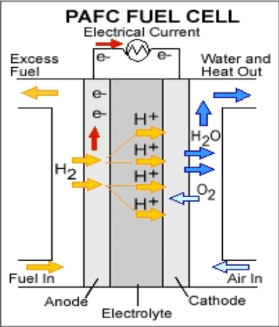
Figure 3. Phosphoric Acid Fuel Cell.
Anode reaction: |
H2 → 2H+ + 2e- |
Cathode reaction: |
½O2 +2H+ + 2e- → H2O |
Overall reaction: |
H2 + ½O2 → H2O |
Proton exchange membrane fuel cell
Proton exchange membrane fuel cells also called polymer electrolyte membrane (PEM) fuel cells (PEMFC), are a sort of fuel cell has been developed for transport applications as well as for stationary fuel cell and portable fuel cell applications. The proton exchange membrane fuel cell is uncommon in that its electrolyte consists of a layer of solid polymer which allows protons to be diffused from one face to the other and widely available PEM materials is the fluoropolymer (PFSA) [12] Nafion, a DuPont product [12]. It mainly needs hydrogen and oxygen as its inputs [13], however, the oxidant may also be ambient air, and these gases must be humidified. It operates at a low temperature because of the restrictions enforced by the thermal properties of the membrane itself. The typical operating temperatures are around 90 °C. The PEMFC can be contaminated by carbon monoxide, and adversely effect on the performance. It requires cooling and management of the exhaust water in order to function properly.
In recent years, the main focus of current designs of this class of fuel cells is in transport applications, as there are advantages to having a solid electrolyte for safety. The heat evolved by the fuel cell is actually not sufficient for any form of cogeneration. Several car manufacturing companies have recently focusing on using fuel cells in their cars. However, the PEMFC still in very small scale of usage for power generation, where the heat could be used for hot water or space heating. There is also the possibility of a heater/chiller unit for cooling in areas where air conditioning is popular. If it does prove possible to use this particular type of fuel cell for transport and power generation, then the advantages generated by economies of scale and synergy between the two markets could make the introduction of the technology easier than in other cases.
Anode reaction: |
H2 → 2H+ + 2e- |
Cathode reaction: |
½O2 +2H+ + 2e- → H2O |
Overall reaction: |
H2 + ½O2 → H2O |
Polymer electrolyte membrane fuel cells are mainly used for transportation applications such as cars and buses and they operate at relatively low temperatures.
(Figure 4)
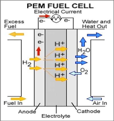
Figure 4. Polymer Electrolyte Membrane Fuel Cell.
3-1 Direct methanol fuel cells
This type of fuel cell uses pure methanol as a fuel. Methanol is also easier to be supplied to the public using existing infrastructure.
The methanol used in direct methanol fuel cell is mixed with steam which is then fed directly to the fuel cell anode. Direct methanol fuel cell technology is relatively new compared to hydrogen fuel cells.
There are several problems with these fuel cells arise from the lower electrochemical activity of the methanol as compared to hydrogen. This gives rise to lower cell voltages and consequently on efficiency. Moreover, methanol is highly miscible with water, so some of it is likely to cross the water-saturated membrane and cause corrosion and exhaust gas problems on the cathode. Because of the methanol cross-over, a phenomenon by which methanol diffuses through the membrane without reacting, methanol is fed as a weak solution: this decreases efficiency significantly, since crossed-over methanol, after reaching the air side (the cathode), immediately reacts with air which consequently reduce the cell voltage. Cross-over remains as a main cause of inefficiencies, and often 50% of the methanol is lost to cross-over. Methanol cross-over and/or its effects can be alleviated by (a) developing alternative membranes [14], (b) improving the electro-oxidation process in the catalyst layer and improving the structure of the catalyst and gas diffusion layers [15], and (c) optimizing the design of the flow field and the membrane electrode assembly (MEA) which can be achieved by studying the current density distributions.[16] Nevertheless, the direct methanol fuel cell is an interesting proposition and a number of places are working on it, including Siemens in Germany, the University of Newcastle and Argonne National Laboratory. There are also efforts to develop a low-temperature SPFC (500°C) that would also allow the direct use of methanol, as well as using stainless steel components.
Anode reaction: |
MeOH + H2O→ CO2 + 6H+ + 6e- |
Cathode reaction: |
3(½O2) + 6H+ + 6e- → 3H2O |
Overall reaction: |
MeOH + H2O+ 3(½O2) → CO2 + 3H2O
(Figure 5) |
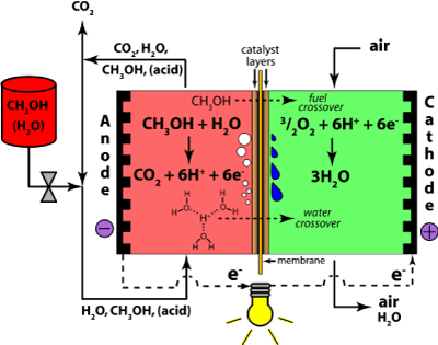
Figure 5. Direct Methanol Fuel Cells.
Molten carbonate fuel cell
Molten carbonate fuel cells (MCFCs) ha2021 Copyright OAT. All rights reservl gas, biogas (produced as a result of anaerobic digestion or biomass gasification), and coal-based power plants for electrical utility, industrial, and military applications. MCFCs are high-temperature fuel cells that use an electrolyte composed of a molten carbonate salt mixture suspended in a porous, chemically inert ceramic matrix of beta-alumina solid electrolyte (BASE). In the molten carbonate fuel cell, the electrolyte consists of a molten mixture of potassium carbonate and lithium carbonate to transport carbonate-ions from the cathode to the anode. The CO32- transport needs supply of CO2 at the cathode side of the cell which is generally be obtained by recycling the anode off side gas. The operating temperature is about 850°C which allows nickel to be used as catalyst material. The process occurring in a hydrogen-oxygen fuel cell operating at higher temperatures without an aqueous electrolyte might well be considered as oxide ions produces at the air electrode:
O2 + 4e- → 2O2-
Which then move to the fuel electrode to oxidize the hydrogen:
H2 + O2- → H2O + 2e-
and can be considered that a molten ionic oxide would offer the best electrolyte to boost this process. Nevertheless, simple ionic oxides have melting points higher than 1000 °C and thus, a great deal of attention has been focused on salts melting at lower temperature. These salts are normally those with oxygen-containing anions, e.g nitrates, sulfates, carbonates. At high temperature, it is likely that the direct reaction of hydrocarbons at the fuel electrode is favorable and that is why the conversion of petroleum products to hydrogen or methanol is pointless. However, consideration must be directed towards the effect of hydrocarbon oxidation at the fuel electrode on the choice of electrolyte. Carbon dioxide will be a major product that can be troublesome with some salts, for example:
CO2 + SO42- → CO32- + SO3
Hence it is most reasonable to consider as electrolyte a molten carbonate or mixture of carbonates. A mixture of salts may have a considerable advantage since it will have a lower melting point than either of its components. An appropriate way of sustaining the carbonate composition of the electrolyte is to eradicate carbon dioxide as a gaseous product from the fuel electrode and relocating it to the oxidant electrode in the air or oxygen stream. Hence, for a fuel such as carbon monoxide the overall electrode processes will be:
O2 + 2CO2 + 4e- → CO32-
and CO + CO32- → 2CO2 + 2e-
Carbonate ion transfer within the electrolyte may be balanced by carbon dioxide transfer outside it. A similar mechanism could operate even for cells using hydrogen as a fuel [17] (Figure 6).
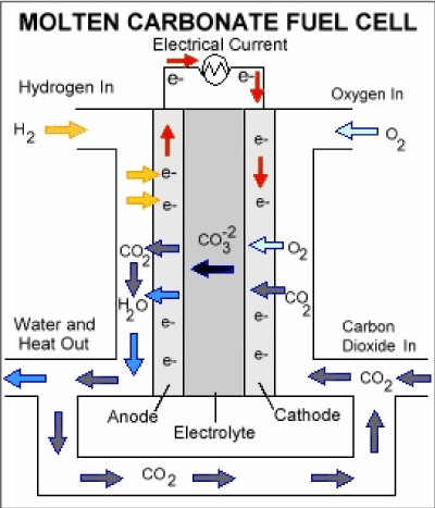
Figure 6. Molten Carbonate Fuel Cell.
Anode reaction: |
H2 + CO32- → CO2 + H2O + 2e- |
Cathode reaction: |
½O2 + CO2 + 2e- → CO32- |
Overall reaction: |
H2 + ½O2 → H2O |
Solid oxide fuel cells
Solid oxide fuel cells (SOFCs) offer a clean technology to electrochemically generate electricity at high efficiencies as their efficiencies are not restricted by the Carnot cycle of a heat engine [18-20].
Solid oxide fuel cells are basically made of solid-state materials, using an ion-conducting oxide ceramic as the electrolyte, and are functioned in the temperature range of 900-1000°C. SOFC offer several advantages compared to other fuel cell types: they bring few problems with electrolyte management (to compare with liquid electrolytes, which are often corrosive and difficult to handle), they have the highest efficiencies of all fuel cells (50-60 %) and for combined heat and power applications internal reforming of hydrocarbon fuels is possible.
Current technology employs several ceramic materials for the active fuel cell components. The anode is normally created from an electronically conducting nickel/yttria-stabilised zirconia cermet (Ni/YSZ). The cathode is based on a mixed conducting perovskite, lanthanum manganate (LaMnO3). Yttria-stabilised zirconia (YSZ) is used as the oxygen ion conducting electrolyte. To generate a suitable voltage, fuel cells in the same stack are interconnect with a doped lanthanum chromate (eg La0.8Ca0.2CrO3) joining the anodes and cathodes of adjacent units. Although several stack designs are being considered around the world, the most common configuration is the planar (or "flat-plate") SOFC.
The high temperature range of SOFC operation is required for the YSZ electrolyte to provide sufficient oxygen ion conductivity. However, the cost to manufacture these devices is, mainly because expensive high temperature alloys must be used for the balance-of-plant structures. These costs would be significantly decreased if the operating temperature could be lowered to between 600-800 °C, allowing the use of cheaper structural components, such as stainless steel. A lower operating temperature would also ensure a greater overall system efficiency and a reduction in the thermal stresses in the active ceramic structures, leading to a longer expected lifetime. To lower the operating temperature of SOFC, either the conductivity of YSZ must be improved, or alternative electrolytic materials must be developed to replace it. A concerted effort is being made by researchers around the globe to develop such materials. Ceramics that are currently being investigated include Gd-doped CeO2, Ba2In2O5 and (Sr,Mg)-doped LaGaO3 . However, these new materials all face serious drawbacks compared with YSZ, and it is most likely that the first commercial SOFC units will use zirconia-based ceramics as the electrolyte.
Anode reactions: |
H2 + O2- → H2O +2e-
CO + O2- → CO2 + 2e- |
Cathode reaction: |
O2 + 4e- → 22- |
Overall reaction: |
H2 + O2 + CO → H2O + CO2 |
(Figure 7) |
|
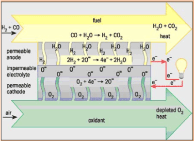
Figure 7. Solid Oxide Fuel Cell.
Advantages and disadvantages of the technology
Advantages
- Fuel cells have a higher efficiency than diesel or gas engines.
- Most fuel cells operate silently, compared to internal combustion engines. They are therefore ideally suited for use within buildings such as hospitals.
- Fuel cells can eliminate pollution caused by burning fossil fuels; for hydrogen fueled fuel cells, the only by-product at point of use is water.
- If the hydrogen comes from the electrolysis of water driven by renewable energy, then using fuel cells eliminates greenhouse gases over the whole cycle.
- Fuel cells do not need conventional fuels such as oil or gas and can therefore reduce economic dependence on oil producing countries, creating greater energy security for the user nation.
- Since hydrogen can be produced anywhere where there is water and a source of power, generation of fuel can be distributed and does not have to be grid-dependent.
- The use of stationary fuel cells to generate power at the point of use allows for a decentralized power grid that is potentially more stable.
- Low temperature fuel cells (PEMFC, DMFC) have low heat transmission which makes them ideal for military applications.
- Higher temperature fuel cells produce high-grade process heat along with electricity and are well suited to cogeneration applications (such as combined heat and power for residential use).
- Operating times are much longer than with batteries, since doubling the operating time needs only doubling the amount of fuel and not the doubling of the capacity of the unit itself.
- Unlike batteries, fuel cells have no "memory effect" when they are getting refueled.
- The maintenance of fuel cells is simple since there are few moving parts in the system.
Disadvantages
1. Hydrogen is currently very expensive, not because it is rare (it’s the most common element in the universe!) but because it’s difficult to generate, handle, and store, requiring bulky and heavy tanks like those for compressed natural gas (CNG) or complex insulating bottles if stored as a cryogenic (super-cold) liquid like liquefied natural gas (LNG).
2. It can also be stored at moderate temperatures and pressures in a tank containing a metal-hydride absorber or carbon absorber, though these are currently very expensive
Conclusion
In the light of the present overview, we conclude that so far, hydrogen can be only produced using abundant and diverse domestic energy resources, such as fossil fuels. Moreover, it has been proven that using hydrogen as a form of energy can not only reduce our dependence on oil, but also positively contribute to alleviate severe environmental impacts caused by emissions from greenhouse gases as well as cars exhausts.
In this review, we highlighted all other categories of fuel cells which basically generate hydrogen gas in their electrochemical reactions. In this regard, we have shed some light on the genuine scientific initiatives to accelerate the research and development of fuel cells and hydrogen production, storage, and delivery infrastructure technologies needed to support hydrogen fuel cells for use in transportation and electricity generation.
We strongly believe that the prospect of hydrogen production and usage is highly linked to the commercialization of all of the aforementioned research effort. This can only be achieved via opening channels with industry and supporting research in this concern. Fortunately, there have been very significant steps towards looking for convenient and eco-friendly fossil fuel alternatives particularly in Europe, and some other countries around the world.
Acknowledgement
A special thank goes to Department of Chemistry, College of Science, Al-Nahrain University for their outstanding assistance to perform this research.
References
- Khurmi RS (2004) Material Science, S Chand & Company Ltd, New Delhi, ISBN 8121901464 (ISBN13: 9788121901468).
- Ali GQ, El-Hiti GA, Tomi I HR, Haddad R, Al-Qaisi, et al. (2016) Photostability and performance of polystyrene films containing 1,2,4-triazole-3-thiol ring system Schiff bases. Molecules 21: 1699. [Crossref]
- Ali MM, El-Hiti GA, Yousif E (2016) Photostabilizing efficiency of poly (vinyl chloride) in the presence of organotin(IV) complexes as photostabilizers. Molecules 21:1151. [Crossref]
- Yousif E, Hasan A, El-Hiti GA (2016) Spectroscopic, physical and topography of photochemical process of PVC films in the presence of Schiff base metal complexes. Polymers 8: 204.
- Yousif E, El-Hiti GA, Hussain Z, Altaie A (2015) Viscoelastic, spectroscopic and microscopic study of the photo irradiation effect on the stability of PVC in the presence of sulfamethoxazole Schiff’s bases. Polymers 7: 2190-2204.
- Yousif E, El-Hiti GA, Haddad R, Balakit AA (2015) Photochemical stability and photostabilizing efficiency of poly (methyl methacrylate) based on 2-(6-methoxynaphthalen-2-yl) propanoate metal ion complexes. Polymers 7:1005-1019.
- Akram E, Shaalan N, Rashad AA, Hasan A, Al-Amiery A, et al. (2016) Study of structural and optical properties of New Films Derived PVC-2-[5- phenyl-1,3,4-thiadiazol-2-ylimino-methyl]-benzoic acid. Research Journal of Pharmaceutical, Biological and Chemical Sciences 7: 2836-2844.
- Prabhu RR (2013) Stationary Fuel Cells Market size to reach 350,000 Shipments by 2022, Renew India Campaign.
- Srivastava HC (2014) Nootan ISC Chemistry, Nageen Prakashan, ISBN 9789382319399. (12th) Edition18: 458-459.
- Nigel S, Roberto B, Knut S (2004) Phosphoric acid fuel cells: Fundamentals and applications. Current Opinion in Solid State and Materials Science 8: 372-378.
- Zhiwei Y (2004) Novel inorganic/organic hybrid electrolyte membranes Preprints of Papers- American Chemical Society. Division of Fuel Chemistry 49: 599.
- Townsend CW, Naselow AB (2008) US Patent 5266421 – Enhanced 59 membrane-electrode interface, assigned to Hughes Aircraft.
- Alternative electrochemical systems for ozonation of water, NASA Tech Briefs (Technical report), NASA. 20 March 2007, MSC-23045. Retrieved 17 January 2015.
- Wei Y, Saif M (2012) A novel membrane for DMFC – Na2Ti3O7 Nanotubes/Nafion® composite membrane: Performances studies. International Journal of Hydrogen Energy 37: 1857-1864.
- Matar S, Hongtan L (2010) Effect of cathode catalyst layer thickness on methanol cross-over in a DMFC. Electrochimica Acta 56: 600-606.
- Almheir S, Hongtan L (2014) Separate measurement of current density under land and channel in Direct Methanol Fuel Cells. Journal of Power Sources 246: 899-905.
- Andrew LD (2004) Molten carbonate fuel cells. Current Opinion in Solid State and Materials Science 8: 379-383.
- Singhal SC, Kendall K (2003) High-temperature Solid Oxide Fuel Cells: Fundamentals, Design and Applications Elsevier, Oxford, UK.
- Singhal SC (2000) Advances in solid oxide fuel cell technology. Solid State Ionics 135: 305-313.
- Shahrukh S, Sudhakar K, Brajesh C, Jamil A (2015) A review on recent advances in proton exchange membrane fuel cells: Materials, technology and applications. Advances in Applied Science Research 6:89-100.


