Nanoindentation corrected for thermal drift has been performed on binderless flexible graphite with a Berkovich tip, and the numerical modelling of the results has been carried out. The nanoindentation load-displacement curves of the samples were obtained under different peak loads ranging from 100 µN to 1 mN. Finite Element Method was applied for analysing the loading and unloading parts of these curves, using an elasto-plastic model and assuming flexible graphite as a continuous medium. The difficulties in determining the mechanical properties of binderless flexible graphite from the nanoindentation load-displacement curves were discussed. Numerical results were compared to experimental nanoindentation curves, and some mechanical parameters of this material were determined for the first time.
Binderless flexible graphite is a commercial carbon material made by compression – rolling of exfoliated graphite particles which, through their mechanical interlocking, lead to a flexible foil of pure graphite. Such material presents a number of favourable features for being used under moderate to high pressures and temperatures, such as: insensitivity to thermal shocks, absence of shrinkage, hardening or hot creep, and outstanding chemical resistance. Additionally, it is easy to cut and to shape, is flexible and homogeneous, and possesses thermal conductivity, elastic recovery, compressibility, low creep rate and friction coefficient[1]. Because of such excellent properties, flexible graphite is widely used as an asbestos substitute for sealing applications in chemical and petrochemical industries, in refineries, and in energy, engineering and automotive sectors. However, it is also commercialised for thermal applications, being used as heating element, thermal screen, or heat dissipation material in the glass industry, or for metal casting and silicon ingot production for example1.
From an academic point of view, flexible graphite has been extensively used as a substrate for investigating phase transitions in adsorbed films [1], due to its exceptional surface homogeneity. Its structure [2-7] and its main physical properties [8-13] as well as its main structure – properties relationships [14-19] have also been thoroughly investigated, and many additional applications than those listed above have been suggested. Among them, electromagnetic interference shielding [20], heating [21], vibration damping [22], electronic [23] and electrochemical devices [24-28], thermal management [29] and even others [30] have been proposed.
Despite so many and major actual or potential applications, binderless flexible graphite has never been investigated by nanoindentation as far as the authors know. Only one recent work [31] reported nanoindentation of exfoliated graphite compacts whose porosity (from 62 to 96%) was far higher than that of the material considered here (50%, see below). Yet, ultra-low load indentation has emerged as an important method for investigating the mechanical response to applied loadings of small material volumes or thin films [32-38]. Local properties of bigger samples can also be determined, which is especially important in composites or in porous materials. One major advantage of such method is the possibility of exploring the first stages of deformation and therefore understanding the role of large plastic deformation [33]. Indentation hardness tests are thus interesting in nearly all areas of materials science and engineering [34]. As far as carbon materials are concerned, micro- or nano-indentation of glasslike carbon [39-43], fullerite films and diamond-like carbon [44-47], graphite [47-50] and other miscellaneous carbon forms [40,51] has been already investigated. Flexible graphite, having a typical porosity of 50%, is expected to have an intermediate behaviour between that of bulk graphite itself and that of highly porous materials made from poorly compressed exfoliated graphite, hence the interest of the present study further supported by its many industrial applications. Moreover, no finite-element analysis has ever been carried out so far.
In a typical nanoindentation test, the load-displacement curves of the indenter into the material are simultaneously registered throughout loading and unloading cycles. The corresponding experimental data can be used to determine the mechanical properties of the indented material as reported elsewhere [52,53]. At small scale, the material’s response is complex and depends on the penetration depth of the indenter. The technique allows evaluating a broad range of materials mechanical behaviour, including work of elastic and plastic deformation, elasto-viscoplastic behaviour, time-dependent behaviour, and creep behaviour. Methods are even currently being developed to enable the determination of stress-strain curves as well. In the present paper, experimental nanoindentation data were used as input to the commercial ABAQUS software using a macroscopic elasto-plastic model. Simulating the mechanical behaviour of nanoindentation tests is much more challenging than FE modelling of classical indentation tests (see for instance [54]). The main objectives for the present work were to characterise binderless flexible graphite response by nanoindentation simulations through comparisons with experimental data, and to show that a numerical procedure can be developed for characterising a porous material based on nanoindentation tests.
Material
A foil of Papyex®, the commercial name of binderless graphite sheet produced by the company Mersen (formerly Le Carbone Lorraine, France), has been used in the present work. It was in the form of a black, shiny and smooth, 1 mm-thick sheet, whose main features are given in Table 1.
Table 1. Main characteristics and properties of Papyex® sheet at room temperature1.
Property |
> 98
< 2
700
1.1
≈ 50
8 - 9 |
Carbon content (wt. %)
Ash content (wt. %)
Sulphur content (ppm)
Bulk density (g cm-3)
Porosity (%)
Peak pore size (nm) |
|
In plane |
Through thickness |
Permeability (cm2 s-1 atm-1)
Thermal expansion (10-6 K-1)
Electrical resistivity (W cm)
Compressibility (%)
Elastic recovery (%)
Tensile strength (MPa)
Thermal conductivity (W m-1 K-1) |
–
≈ 0
0.001
–
–
4.5
160 |
10-5
25 – 28
0.05
45 – 52
10 – 15
–
4 |
Nanoindenter and measurement principles
The measurements were performed with an ultra-nanoindenter (Anton Paar, formerly CSM Instruments, Switzerland). The specificity of this apparatus is the continuous, active, correction of the thermal drift through the use of a reference head already in contact with the sample. The indenter displacement is thus measured differentially to this reference. In other words, the motion of the indentation tip is always relative to any movement of the sample or thermal drift of the body, which, with a classical static system, would cause error due to elasticity of the sample or compliance of the supporting framework, or to temperature fluctuations. With the present system, the thermal drift was about 0.5 nm min-1, all the tests lasting much less than 5 min. The values of load noise floor and depth noise floor were as low as 0.13 µN and 0.03 nm, respectively.
The measurement method of the instrumented indentation test is given in detail by ISO 14577-1 standard, Part 1[2]. During the nanoindentation test, the sample was moved at 3000 nm min-1 by the vertical table in order to touch the reference. The servo loop of the reference was then activated with a contact load of 10 µN. The indenter approach was performed by a piezo actuator, and the contact was detected with the indenter load sensor. The indentation cycle was run using the piezo actuator in servo loop mode to generate the load, and using both the depth sensor and the load sensor to measure the penetration depth and the normal load.
A diamond Berkovich-type indenter, i.e., pyramidal with triangular base, was used, whose geometry is shown in Figure 1a. The Berkovich tip has an equilateral triangle as the base and an angle of 65.03° between the axis of the pyramid and the three faces. The elastic recovery of flexible graphite prevented the direct observation by optical microscopy of the residual indent after application of a 100 µN load, as the indent had a size lower than 1 µm. Applying 500 µN led to an easily observed indent, and the latter was even more easily seen after loading at 1 mN. Figure 1b shows the residual indent after application of the Berkovich indenter at 1 mN.
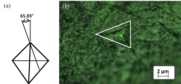
Figure 1. (a) Geometry of Berkovich indenter; (b) Optical micrograph of the indent in flexible graphite after loading at 1 mN with a Berkovich tip.
The validity of nanoindentation for characterising a porous material such as binderless flexible graphite might be questioned. However, based on the detailed woks reviewed elsewhere [16,55] and on the values given in Table 1, it is known that such pores are not only extremely narrow, and therefore are negligibly small with respect to the indentation depth and width, but are flat, highly oriented and homogeneously distributed all over the bedding plane of the individual graphite microdiscs of which the material is made. As a result, no effect of the indenter location was expected, nor was experimentally observed. Additionally, the surface of flexible graphite is very smooth at the macroscopic scale, explaining its highly shiny, almost mirror-like, aspect. At the nanoscale, the typical roughness determined by AFM is of the order of 100 nm [56], i.e., is 8 to 30 times lower than the indentation depths used in this work (see below). Therefore, the surface roughness was not expected to influence significantly the results. In our tests, 20 different zones of the surface were indented, and only 2 had to be discarded as the corresponding results exceeded the average behaviour by more than 10%, either due to a different crystallite orientation or to any other kind of defect, further supporting the homogeneity of the material and the applicability of nanoindentation.
Determination of elastic modulus
The deformation process occurring during nanoindentation is schematically illustrated in Figure 2a. As the indenter is driven into the material, both elastic and plastic deformation occurs, which results in the formation of a typical hardness imprint conforming to the shape of the indenter to some contact depth, hc. During indenter withdrawal, only the elastic portion of the displacement is recovered, which facilitates the use of elastic solutions in modelling the contact process.
Figure 2b shows a typical set of load-displacement data, with which useful experimental quantities involved in the measurement can be defined. These quantities are the peak load, Pmax, the displacement at peak load, hmax, the depth of the permanent deformation of the test piece, hp, and the intercept of the tangent line to the unloading curve at the maximum test force with the indention depth axis, hr. The unloading stiffness  is calculated by differentiating the indentation load P at the maximum depth of penetration h = hmax (Figure 2b).
From the load-displacement data shown in Figure 2b, the projected contact area of the hardness imprint, A, is estimated by evaluating an empirically determined indenter shape function at the contact depth hc, that is A = A(hc). For a geometrically perfect Berkovich indenter, the shape function A(h) relating the cross-sectional area of the indenter to the distance h from its tip reads [57]:
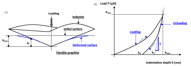
Figure 2. (a) Deformation process in a nanoindentation test (after [34]); (b) Typical indentation force-penetration curve during nanoindentation test.
A=A(h)=24.5h2 (1)
Pharr et al. [58] have shown that mechanical response depends on the geometry of the indenter, leading to the following equation for the effective elastic modulus Eeff:
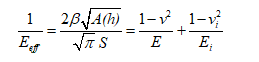 (2)
(2)
where b = 1.034 for Berkovich indenter, E and n are Young’s modulus and Poisson’s ratio of the sample, and Ei and ni are the same quantities for the Berkovich indenter (for diamond: Ei = 1141 GPa and ni = 0.07).
The great progresses of continuum mechanics are related to the corresponding predictive models, based on a relatively low number of measurable parameters. From the latter, an excellent description of the mechanical behaviour of materials at different length scales can be achieved, thereby enabling the construction of buildings, bridges, planes, and automobiles. Many mechanical properties of materials are structure- and/or size-dependent. For instance, Young’s modulus is not size-dependent, as the measured values at the macroscopic scale agree with those predicted from quantum mechanics calculations. In contrast, other properties such as yield stress of polycrystalline solids are size-dependent, as they may take different values, depending on the grain size[3] [59,60].
In the present work, we present a simple macroscopic model for describing the elasto-plastic behaviour of binderless flexible graphite. The model allows detailed analysis of nanoindentation tests, thus providing information that might have been obscured if more complex mechanical models had to be used. It should be stressed here that it is not the first time that a porous material is considered homogeneous for the numerical simulation of its properties in the context of continuum mechanics [61,62]. Moreover, as shown in Table 1, the characteristic pore size is close to 10 nm, i.e., typically two orders of magnitude lower than both indentation depths and indent size, at which the properties of flexible graphite were determined as explained below.
Theoretical aspects
The isotropic elasto-plastic constitutive equations were developed using the classical thermodynamics of irreversible processes with state variables [61-66]. The choice of a macroscopic computational model for simulating nanoindentation tests might seem surprising for being applying to flexible graphite. However, such approach was already shown to be quite efficient for modelling the mechanical behaviour of materials submitted to nanoindentation tests [54].
Four couples of internal state variables were used for this isothermal case:  for the plastic flow and (r, R) for the isotropic hardening, related to each other according to the constitutive, following, equations.
Conjugate stress-like variables:
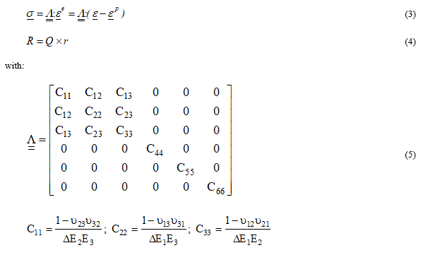
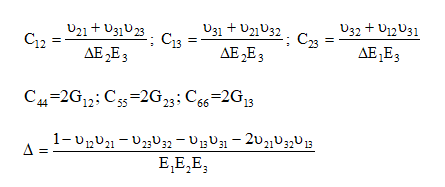
and where σ is the tensor of Cauchy stress;  is the tensor of elastic strain; ε is the tensor of total strain;
  is the tensor of plastic strain.
  is the fourth order symmetric elastic properties tensor, and is a function of the Young’s moduli Ei in the direction i, of shear moduli Gij, and of Poisson’s ratios nij in the plane (i-j). Finally, R is the isotropic hardening stress, r is the isotropic hardening rate, and Q is the isotropic hardening modulus.
Flux variables:
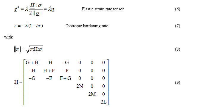
and where is the plastic multiplier,
 is the fourth order operator reflecting Hill anisotropy, n is the normal to the loading surface f (see below), and b is the non-linear isotropic hardening coefficient. The Hill criterion f is given as follows, which is a function of six parameters, F, G, H, L, M and N [61,62]:

where  is the limit yield stress.
These equations give the classical elasto-plastic constitutive equations and were implemented into the ABAQUS/Explicit FE software[4].
Numerical aspects
The tensor of plastic strains was obtained using the q-method, and the isotropic hardening variable rn+1 was obtained with the asymptotic method, i.e.:
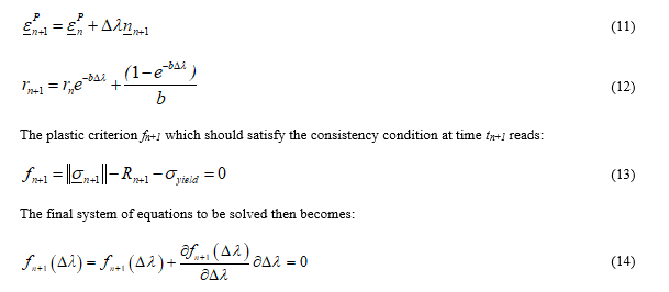
This non-linear algebraic system can be solved by using the iterative Newton-Raphson procedure in order to determine the unknown  . The approach of Simo and Hughes [67] consists in decomposing the problem in two steps: an elastic prediction step, where the problem is supposed to be purely elastic, and a plastic correction in which the plasticity criterion is satisfied.
Elastic prediction:
Given a total strain increment at time tn, assuming the response to be initially elastic, the trial stress at time tn+1 was obtained as:
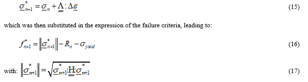
 the obtained response is elastic, and the tensorial quantities at time tn+1 were obtained as :

Plastic correction:
Otherwise, if  , then it became necessary to apply a correction to the trial stresses
  to obtain
 and
and  such that:
The principle of virtual power written on the current deformed configuration with the volume (Ω) and boundary (Γ) was discretised thanks to the velocity-based FE method and led, after the assembly operation, to the following global nonlinear algebraic system3:

where [Mn] is the mass matrix, and {Rn} the residual vector.
The explicit algorithm consisted in obtaining solutions at the time tn+1 = tn + Δt based on solutions obtained at the previous times:
where  is the acceleration vector at time tn,
  is the velocity vector at half step, and {Un+1} is the displacement vector at final time tn+1.
Contact force computation and Coulomb friction model
In nanoindentation tests, contact and friction play a central role at the interfaces between the Berkovich indenter and the sample. Coulomb friction model is used for most contact problems with friction, and reads:

where µ is the friction coefficient, and  is the tangential force to the normal force
  at any point of the contact interface [68,69].
In ABAQUS software, the contact interface conditions were taken into account using the penalty method based on the master/slave surfaces approach. The friction constitutive equation was modelled by the well-known Coulomb model characterised by the single friction parameter µ such that 
Nanoindentation tests
Twenty identical nanoindentation tests were carried out perpendicularly to the surface of the sheet of flexible graphite. The maximum indentation displacement was 3000 nm. For each zone of the surface, nanoindentation was carried out at different loads, P, ranging from 0.1 to 1 mN. All tests, with the exception of only two indented zones that were discarded, led to nearly identical load–displacement curves, i.e., differing by less than 10%. Representative examples of such curves are presented in Figure 3. The loading part of the nanoindentation curves involves nonlinearity induced by the nonlinear material behaviour and by the increasing contact area (geometrical nonlinearity). The unloading part of the nanoindentation curves is purely elastic. As the contact area decreases with the decrease of the indentation depth, geometrical effects lead to a nonlinear unloading curve.
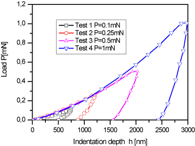
Figure 3. Experimental load-displacement curves at different loads indicated in the inset, leading to four different indentation depths.
FE method modelling
This section deals with the simulation of the nanoindentation process with the main objective of determining the elasto-plastic properties of binderless flexible graphite. Since the nanoindentation results have been obtained with the Berkovich indenter, we have simulated the process using an axisymmetric model which allows mesh definition with a restricted number of degrees of freedom [70-72].
Axisymmetric model:
Figure 4 schematically illustrates the FE model and boundary conditions, where roller boundary conditions were applied both along the axis of symmetry and along the axis of the sample base. The specimen of flexible graphite was represented by a mesh consisting of 3600 elements type CAX4R available in ABAQUS/Explicit (4-node axisymmetric reduced integration elements)4. The specimen was 40 µm wide and 40 µm long. The Berkovich tip was modelled as a conical indenter using 24 elements type RAX2 available in ABAQUS/Explicit (2-node linear axisymmetric rigid elements)4, as shown in Figure 4. Such a movable, rigid, conical indenter having a 70.3° half-angle, is indeed known to be an excellent approximation of the pyramidal Berkovich tip [70,72], as it provides the same indentation depth to projected area ratio. Additionally, the use of a 2D, axisymmetric, conical-shaped model indenter allows saving significant computational resources [73 and refs. therein]. The simulations were carried out using a displacement rate of 1 mm min-1 and by considering a density of 1.1 g cm-3.
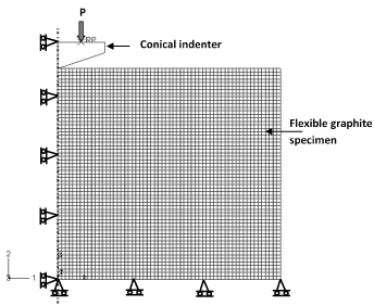
Figure 4. FE model and boundary conditions.
The contact between the rigid Berkovich indenter and the sample was simulated using classical isotropic Coulomb friction model with a friction coefficient µ = 0. The nanoindentation process was simulated both during loading and unloading steps. In the loading process, the simulation was performed to a depth of 3000 nm, corresponding to a load of 1 mN in the vertical direction. During the process of unloading, the indenter tip returned to its original position. The controlled displacement method was applied in the simulations.
Model parameters identification
The material parameters, elasticity and plasticity, were determined as explained below by using a combination of numerical simulations and experimental data obtained from nanoindentation tests. The corresponding values have been reported in Table 2.
Table 2. Material properties determined in the present work for binderless flexible graphite.
Elasticity |
Young’s modulus, Ei = E = 190 MPa
Poisson’s ratio, nij = n = 0.3 |
Plasticity |
Yield stress, syield = 1.9 MPa
Hill’s parameters, F = G = H = 0.5, L = M = N = 1.5
Isotropic hardening modulus, Q = 0.7 MPa
Non-linear isotropic hardening coefficient, b = 13 |
Elastic properties: The elastic parameters of binderless flexible graphite are unknown, and the actual elastic response is expected to be orthotropic. Herein, the elastic properties were determined from the unloading parts of the experimental nanoindentation curves only, as it is well known that such unloading part is highly sensitive to elastic parameters [37,74]. The data which were used in the simulations are shown in Figure 5. The comparison between numerical and experimental results allowed the determination of the elastic properties listed in Table 2.
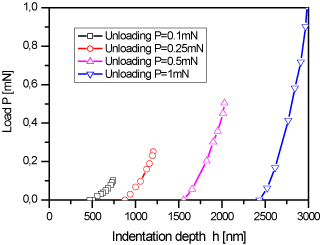
Figure 5. Unloading part of experimental nanoindentation curves obtained for the four different indentation depths.
Figure 6 shows the changes of Young’s modulus, E, as a function of indentation depth, calculated from the experimental nanoindentation tests using Eqs. (1) and (2). E clearly decreased when the indentation depth increased. Such behaviour may be explained by two facts:
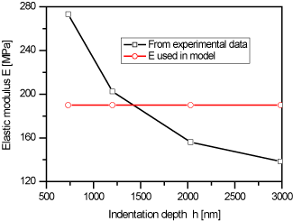
Figure 6. Young’s modulus calculated from experimental results as a function of indentation depths, and comparison with the simulated value.
- The combination of Eqs (1) and (2) shows that E decreases when the penetration depth h increases;
- Flexible graphite was prepared by compression-rolling and, as always observed in all boards made this way, the density profile presents a shallow minimum at mid-thickness. Therefore, the drop of density which is the most significant just beneath the surface leads to a decrease of measured modulus. Such effect is not compensated by the expected densification which is likely to occur when compressing a porous material because this material is highly elastic, hence its use for seals and gaskets.
The horizontal line at 190 MPa in Figure 6 is the value of E used for different indentation depths in the simulations. As such value is very close to the average of the experimental results, it can be concluded that the modelling works well.
Plastic properties: Plastic parameters were determined using the nanoindentation curves obtained under different peak loads ranging from 100 µN to 1 mN, as shown in Figure 7. In the simulations, the yield stress, syield, and the hardening parameters, Q and b, were assumed to be identical for each different peak load. Due to the difficulty of obtaining more optimised values, as no more refined optimisation protocol was developed, the values of syield, Q and b were chosen as those already given in Table 2. For clarity, only the set of numerical results obtained from the FE model in the case of an applied load of 1 mN was shown here and compared to the experimental nanoindentation data of Figure 7. A good agreement between both sets of data was obtained.
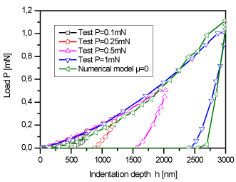
Figure 7. Experimental nanoindentation curves for different indentation depths, and comparison with the numerical simulation for an applied load of 1 mN.
Discussion of measured and calculated values: The values listed in Table 2 deserve the following comments. It should be first emphasised that such data have never been reported elsewhere, as the only available values correspond either to macroscopic measurements made on flexible graphite sheets, or to micro- or nanoindentation measurements carried out on exfoliated graphite compacts of much lower density, or on other kinds of carbonaceous materials. In the former set of data, a value of compressive modulus through thickness of 27 000 psi, i.e., of 186 MPa, has been provided for GrafoilTM,[5] a registered trademark of Union Carbide corresponding to the American counterpart of the European Papyex®. Such a value is in excellent agreement with the 190 MPa given in Table 2 and used in our simulations. It is also consistent with the equation given elsewhere [56] describing the through-thickness compression modulus measured of compressed exfoliated graphite: at a porosity of 50%, one gets 169 MPa. A Poisson’s ratio of 0.25 was given in [75], close to the value of 0.3 that we have taken, and which was also successfully used by other authors [76,77].
The second set of data, obtained from indentation tests, corresponds to Young’s moduli of HOPG, 10.5 GPa [47], of graphite flakes and spherulites in cast iron, 50 GPa and 28 GPa, respectively [50], of pyrolytic graphite, 7.5 GPa [40], of glassy carbon, 20.4-20.8 GPa [40], of coke, 27.6 GPa [40], of carbon-carbon composite elements, around 15 to 30 GPa depending on the element (carbon matrix or carbon fibre, and depending on the orientation of the latter with respect to applied load) [78], and of glasslike carbon treated at different temperatures, from around 31 GPa at 1000°C to around 21 GPa at 3000°C [41]. Elastic moduli of many other carbons, mainly measured by nanoindentation but also by other techniques, have been also compiled in [79]. All these values are consistent with the elastic modulus widely accepted for polycrystalline graphite in general, 7 – 11 GPa, and for graphite single crystal along c-axis in particular, 36.5 GPa [77]. They are significantly higher than the value of 190 MPa reported in the present work, and the high porosity of flexible graphite is indeed expected to lead to dramatically lower the elastic modulus. For instance, indentation of porous cokes led to moduli of 10.5 and 5.3 GPa at 35 and 48% porosity, respectively [40]. Models have indeed been developed, predicting the significant, porosity-induced, drop of modulus and hardness measured by nanoindentation [80,81]. In contrast, dramatically lower values of modulus have been reported for exfoliated graphite compacts of much higher porosity than in the present flexible graphite, ranging from 125 to 250 kPa [31]. In the latter paper, even the modulus measured by nanoindentation of a commercial flexible graphite of density 0.86 g cm-3 (from Mineral Seal Corp., USA) did not exceed 1.7 MPa [31]. However, those values were much more sensitive than ours to the applied load and were obtained at much lower penetration depth, and therefore it is difficult to conclude whether similar moduli would have been obtained if the tests had been carried out in comparable conditions.
The yield stresses reported so far, 1.2 GPa for glassy carbon [40], 1.64 GPa for coke [40], and 0.3-0.4 GPa for graphite single crystal [48], are also 2-3 orders of magnitude higher than the 1.9 MPa found here for flexible graphite. The combined effects of porosity and nanoscale, at which the size of the probed sample influences the result [59,60], may explain this.
Whatever the carbon material, no value of the hardening parameters, Q and b, with which our data might be compared, could be found in the literature. They are indirectly related to the hardness, H, which is very often estimated from nanoindentation measurements, according to:

where Pmax and A(h) have the same meaning as in section 2.3. However, as the equations for describing the indentation behaviour are different, there is no possible comparison of Q and b with H. Application of Eq. (28) to the data of Figure 3 led to the following, average, hardness values: 16.0, 10.9, 7.3 and 5.8 MPa for flexible graphite submitted to loads of 0.1, 0.25, 0.5 and 1 mN, respectively. These values are typically 3 orders of magnitude lower than those reported for bulk carbons: 2 and 0.6 GPa for graphite flakes and spherulites in cast iron [50], 2.35 GPa for HOPG [47], 1.3-3.1 GPa for carbon-carbon composites, depending on the component [78], and 2-3.3 GPa for glasslike carbon derived from phenolic resin [82]. Again, such difference is due to the high porosity of flexible graphite, making it highly deformable with the elastic recovery which is very useful for applications as seals and gaskets.
Finally, the indentation loading-unloading cycles shown in Figure 3 presented small flat tops, neglected in the modelling such as that shown in Figure 7, whose lengths correspond to creep. This feature was not observed for commercial flexible graphite of density 0.86 g cm-3 [31] at a maximum nanoindentation depth of 230 nm. Measurement of such horizontal segments on experimental curves led to values of creep of 5 ± 1%, on average. These values are a little higher than those reported for GrafoilTM, around 3% at room temperature[6].
Von Mises equivalent stress distribution
The distribution of the Von Mises stress at different displacements during the nanoindentation tests under loading at P = 1 mN is shown in Figure 8a. At a displacement of h = 50 nm, stress concentration zones appeared having the form of circles in the contact region between the rigid indenter and the specimen. These zones expanded as the rigid indenter further penetrated into the sample. A significant change of the contour of the Von Mises equivalent stress distribution was observed when the conical indenter started to return to its original position in the unloading part of the load-penetration curve during nanoindentation tests, see Figure 8b. The latter also indicates that tensile stress zones became larger and larger when the indentation displacement increased, causing more significant pile-ups.
The numerical load–displacement curves during the nanoindentation test are shown in Figure 8c with some calculated deformed configurations of the flexible graphite specimen. This figure clearly shows how different are the stress distributions during loading and unloading, and how a permanent imprint is left at the surface of the sample.
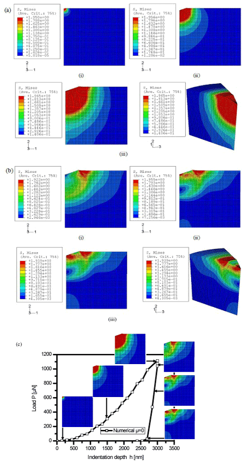
Figure 8. Contour of the Von Mises stress at different indentation depths: (a) loading part only, with (i) h = 50 nm; (ii) h = 1500 nm; (iii) h = 3000 nm; (b) unloading part only, with (i) h = - 50 nm; (ii) h = - 1500 nm; (iii) h = - 3000 nm; (c) Numerical load–displacement curves and corresponding, predicted, specimen shapes.
Other predictions from FE simulations
In this subsection, the effect of mechanical parameters such as yield stress and friction coefficient, known to have an influence during the nanoindentation tests, were also investigated by FE simulations. It may be useful to recall here that the coefficients Q and b of Table 2 have not been optimised independently, as explained in subsection 4.2.2.2, so that other values may have also worked. Herein, Q was indeed just chosen lower than the yield stress and such that the ratio Q/b accounted correctly for the experimental results. The impact of the values of Q and b was thus not considered below.
Yield stress effect: Figure 9 shows the load–displacement curves for an applied load P = 1 mN (loading part only) at different yield stresses. With higher yield stresses syield, higher loads were required to reach a given, fixed, indentation depth. The best agreement between numerical and experiment results was obtained with syield = 1.9 MPa, hence this value was reported in Table 2.
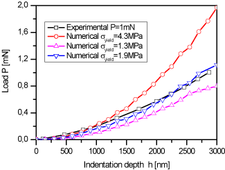
Figure 9. Experimental and calculated load–displacement curves for different yield stresses.
Friction coefficient effect: The FE simulations carried out so far focused on a frictionless contact between the Berkovich indenter and the flexible graphite specimen, i.e., the value of the friction coefficient µ was set to zero. Such choice is supported by the only available data reported so far, corresponding to the friction coefficient of GrafoilTM against steel, and which is indeed very low: 0.018, 0.052 and 0.157 at 0.03 MPa, 0.06 MPa and 0.157 MPa, respectively6. However, friction does play a role at the contact surface and can change the surface profile. For investigating this effect, Coulomb frictional contact was introduced in the FE simulation of nanoindentation tests. Because the value of µ was unknown, we used several values of coefficients between 0 and 0.5 in the simulations, attempting to find a coefficient that would lead to the same surface profile as that experimentally measured. Figure 10 shows that the calculated curves of applied load versus indentation depth were all very similar, irrespective to the values of µ in the interval 0-0.5.
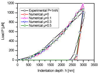
Figure 10. Experimental and calculated load–displacement curves for different friction coefficients.
The objective of this work was to propose a simple numerical methodology for determining the mechanical properties of binderless flexible graphite from nanoindentation tests. We believe that such numerical procedure can be extended to other porous materials characterised by nanoindentation. The model took into account the main mechanical phenomena involved, such as orthotropic elastic behaviour, anisotropic plastic with nonlinear isotropic hardening, large plastic deformations occurring during nanoindentation tests, and contact and friction between the rigid indenter and the comparatively soft sample. This model, which was presented here from both theoretical and numerical aspects, was implemented in ABAQUS/Explicit software using the Vumat user’s subroutine.
The quality of the results obtained in terms of distribution of mechanical stresses, as well as of prediction of the experimental nanoindentation curves obtained under different peak loads ranging from 100 µN to 1 mN, was very satisfactory. Therefore, several mechanical parameters of flexible graphite could be determined for the first time, such as:
- The elastic properties (E = 190 MPa and n = 0.3), determined using the unloading part of the nanoindentation curves. The identification of the elastic parameters was demonstrated to be sufficient;
- The plastic parameters (σyield = 1.9 MPa, Q = 0.7 MPa and b = 13), determined using the loading part of the nanoindentation curves. Due to the difficulty to obtain better optimised values of σyield, Q and b, they were set as constants in the simulations.
Other conclusions arising from the present work are that:
- The penetration load P applied by Berkovich indenter increased with the yield stress σyield;
- The curves of penetration load P versus indentation depth were independent from the friction coefficient µ.
The authors are indebted to Guillaume Berthout (CSM Instruments, Switzerland) for providing experimental nanoindentation data. The authors also gratefully acknowledge the financial support of the CPER 2007-2013 “Structuration du Pôle de Compétitivité Fibres Grand’Est” (Competitiveness Fibre Cluster), through local (Conseil Général des Vosges), regional (Région Lorraine), national (DRRT and FNADT) and European (FEDER) funds.
[2]ISO (2002) 14577-1, -2, -3, Metallic Materials – Instrumented Indentation Test for Hardness and Materials Parameters – Part 1: Test Method, Part 2: Verification and Calibration of Testing Machines, Part 3: Calibration of Reference Blocks. ISO, Geneva, Switzerland.
[4]ABAQUS, Theory manual, version 6.2. Hibbit, Karson & Sorensen, Inc.; 2000.
- Bockel C, Coulomb JP, Dupont-Pavlovsky N (1982) Comparison of the adsorptive properties of Papyex and uncompressed exfoliated graphite. Surf Sci 116: 369-379.
- Gilbert EP, Reynolds PA, White JW (1998) Characterisation of a basal-plane-oriented graphite. J Chem Soc Faraday Trans 94: 1861-1868.
- Finkelstein Y, Nemirovsky D, Moreh R, Kimmel G (2000) Study of the Papyex structure using neutron Compton scattering. Physica B 291: 213-218.
- Gu J, Leng Y (1999) Study of the surface topography of graphite materials using atomic force microscopy. Carbon 37: 991-994.
- Celzard A, Schneider S, Marêché JF (2002) Densification of expanded graphite. Carbon 40: 2185-2191.
- Celzard A, Marêché JF, Furdin G (2002) Surface area of compressed expanded graphite. Carbon 40: 2713-2718.
- Kobayashi M, Toda H, Takeuchi A, Uesugi K, Suzuki Y (2012) Three-dimensional evaluation of the compression and recovery behavior in a flexible graphite sheet by synchrotron radiation microtomography. Mater Charact 69: 52-62.
- Toda H, Tsubone K, Shimizu K, Uesugi K, Takeuchi A, et al. (2013) Compression and recovery micro-mechanisms in flexible graphite. Carbon 59: 184-191.
- Marotta EE, Mazzuca SJ, Norley J (2005) Thermal joint conductance for flexible graphite materials: analytical and experimental study. IEEE Trans Compon Packaging Technol 28: 102-110.
- Luo X, Chung DDL (2001) Flexible graphite under repeated compression studied by electrical resistance measurements. Carbon 38: 985-990.
- Chen PH, Chung DDL (2012) Dynamic mechanical behavior of flexible graphite made from exfoliated graphite. Carbon 50: 283-289.
- Wei XH, Liu L, Zhang JX, Shi JL, Guo QG (2010) Mechanical, electrical, thermal performances and structure characteristics of flexible graphite sheets. J Mater Sci 45: 2449-2455.
- Ionov SG, Avdeed VV, Kuvshinnikov SV, Pavlova EP (2000) Physical and chemical properties of flexible graphite foils. Mol Cryst Liquid Cryst A 340: 349-354.
- Dowell MB, Howard RA (1986) Tensile and compressive properties of flexible graphite foils. Carbon 24: 311-323.
- Celzard A, Marêché JF, Furdin G (2003) Describing the properties of compressed expanded graphite through power laws. J Phys Condens Matter 15: 7213-7226.
- Celzard A, Marêché JF, Furdin G (2005) Modelling of exfoliated graphite. Prog Mater Sci 50: 93-179.
- Leng Y, Gu J, Cao W, Zhang TY (1998) Influences of density and flake size on the mechanical properties of flexible graphite. Carbon 36: 875-881.
- Reynolds RA, Greinke RA (2001) Influence of expansion volume of intercalated graphite on tensile properties of flexible graphite. Carbon 39: 473-481.
- Gua J, Leng Y, Gao Y, Liu H, Kang F, Shen W (2002) Fracture mechanism of flexible graphite sheets. Carbon 40: 2169-2176.
- Luo X, Chung DDL (1996) Electromagnetic interference shielding reaching 130 dB using flexible graphite. Carbon 34: 1293-1294.
- Chugh R, Chung DDL (2002) Flexible graphite as a heating element. Carbon 40: 2285-2289.
- Luo X, Chung DDL (2000) Vibration damping using flexible graphite. Carbon 38: 1499-1524.
- Luo X, Chugh R, Biller BC, Hoi YM, Chung DDL (2002) Electronic applications of flexible graphite. J Electron Mater 31: 535-544.
- Lee S, Seo S, Jin Y, Shim H, Kim D (2010) A graphite foil electrode covered with electrochemically exfoliated graphene nanosheets. Electrochem Commun 12: 1419-1422.
- Fu Y, Hou M, Liang D, Yan X, Fu Y, et al. (2008) The electrical resistance of flexible graphite as flow field plate in proton exchange membrane fuel cells. Carbon 46: 19-23.
- Zhang H, Hsing I (2007) Flexible graphite-based integrated anode plate for direct methanol fuel cells at high methanol feed concentration. J Power Sources 167: 450-454.
- Yazicia MS, Krassowskia D, Prakash J (2005) Flexible graphite as battery anode and current collector. J Power Sources 141: 171-176.
- Hariprakash B, Gaffoor SA (2007) Lead-acid cells with lightweight, corrosion-protected, flexible-graphite grids. J Power Sources 173: 565-569.
- Hu K, Chung DDL (2011) Flexible graphite modified by carbon black paste for use as a thermal interface material. Carbon 49: 1075-1086.
- Chung DDL (2000) Flexible graphite for gasketing, adsorption, electromagnetic interference shielding, vibration damping, electrochemical applications, and stress sensing. J Mater Eng Perf 9: 161-163.
- Chen PH, Chung DDL (2015) Elastomeric behaviour of exfoliated graphite, as shown by instrumented indentation testing. Carbon 81: 505-513.
- Pharr GM (1998) Measurement of mechanical properties by ultra-low load indentation. Mat Sci Eng A 253: 151-159.
- Sahin O, Uzun O, Kölemen U, Uçar N (2008) Mechanical characterization for ß-Sn single crystals using nanoindentation tests. Mater Charact 59: 427-434.
- Cheng YT, Cheng CM (2004) Scaling, dimensional analysis, and indentation measurements. Mat Sci Eng R 44: 91-149.
- Ahn JH, Jeon EC, Choi Y, Lee YH, Kwon D (2002) Derivation of tensile flow properties of thin films using nanoindentation technique. Curr Appl Phys 2: 525-531.
- Xu ZH, Li X (2008) Effects of indenter geometry and material properties on the correction factor of Sneddon’s relationship for nanoindentation of elastic and elastic-plastic materials. Acta Mater 56: 1399-1405.
- Gerday AF, Ben Bettaieb M, Duchêne L, Clement N, Diarra H, Habraken AM (2011) Material behaviour of the hexagonal alpha phase of a titanium alloy identified from nanoindentation tests. Eur J Mech A 30: 248-255.
- Lucca DA, Herrmann K, Klopfstein MJ (2010) Nanoindentation: Measuring methods and applications, CIRP. Ann Manuf Technol 59: 803-819.
- Sakai M, Hanyu H, Inagaki M (1995) Indentation-induced contact deformation and damage of glasslike carbon. J Am Ceram Soc 78: 1006-1012.
- Field JS, Swain MV (1996) The indentation characterization of the mechanical properties of various carbon materials: glassy carbon, coke and pyrolytic graphite. Carbon 34: 1357-1366.
- Iwashita N, Swain MV, Field JS, Ohta N, Bitoh S (2001) Elasto-plastic deformation of glass-like carbons heat-treated at different temperatures. Carbon 39: 1525-1532.
- Swain MV, Field JS (1996) Investigation of the mechanical properties of two glassy carbon materials using pointed indenters. Philos Mag A 74: 1085-1096.
- Iwashita N, Field JS, Swain MV (2002) Indentation hysteresis of glassy carbon materials. Philos Mag A 82: 1873-1881.
- Gupta BK, Bhushan B, Capp C, Coe JV (1994) Materials characterization and effect of purity and ion implantation on the friction and wear of sublimed fullerene films. J Mater Res 9: 2823-2838.
- Richter A, Ries R (1999) Mechanical properties of fullerite and diamondlike carbon films using surface acoustic waves and nanoindentation. Proc SPIE 3725, International Conf on Solid State Crystals '98: Epilayers and Heterostructures in Optoelectronics and Semiconductor Technology, Zakopane (Poland), p. 94.
- Li X, Bhushan B (1999) Micro/nanomechanical and tribological characterization of ultrathin amorphous carbon coatings. J Mater Res 14: 2328-2337.
- Richter A, Ries R, Smith R, Henkel M, Wolf B (2000) Nanoindentation of diamond, graphite and fullerene films. Diamonds Related Mater 9: 170-184.
- Barsoum MW, Murugaiah A, Kalidindi SR, Zhen T, Gogotsi Y (2004) Kink bands, nonlinear elasticity and nanoindentations in graphite. Carbon 42: 1435-1445.
- Shibata T, Sumita J, Tada T, Sawa K (2008) Development of non-destructive evaluation methods for degradation of HTGR graphite components. J Nuclear Mater 381: 204-209.
- Pradhan SK, Nayak BB, Sahay SS, Mishra BK (2009) Mechanical properties of graphite flakes and spherulites measured by nanoindentation. Carbon 47: 2290-2299.
- Sakai M, Nakano Y, Shimizu S (2002) Elastoplastic indentation on heat-treated carbons. J Am Ceram Soc 85: 1522-1558.
- Sasaki T, Yang M, Fukushima S, Tsukano R (2004) Development of the CAEassisted nano-indentation method for the evaluation of the anisotropic mechanical-properties of thin films. J Mater Process Tech 151: 263-267.
- Yan J, Karlsson AM, Chen X (2007) Determining plastic properties of a material with residual stress by using conical indentation. Int J Solids Struct 44: 3720-3737.
- Khelifa M, Fierro V, Celzard A (2014) Finite element simulation of nanoindentation tests using a macroscopic computational model. J Mech Sci Technol 28: 3209-3217.
- Gu JL, Leng Y, Gao Y, Kang FY, Chen WC (1999) Microstructure effect on mechanical properties of flexible graphite sheet. Proc 24th Biennal Conference on Carbon, Charleston, SC (USA), pp. 658-659.
- Krzesiñska M, Celzard A, Marêché JF, Puricelli S (2001) Elastic properties of anisotropic monolithic samples of compressed expanded graphite studied with ultrasounds. J Mater Res 16: 606-614.
- Shokrieh MM, Hosseinkhani MR, Naimi-Jamal MR, Tourani H (2013) Nanoindentation and nanoscratch investigations on graphene-based nanocomposites. PolymTest 32: 45-51.
- Pharr GM, Oliver WC, Brotzen FR (1992) On the generality of the relationship among contact stiffness, contact area, and elastic modulus during indentation. J Mater Res 7: 613-617.
- Liu Y, Wang B, Yoshino M, Roy S, Lu H, et al. (2005) Combined numerical simulation and nanoindentation for determining mechanical properties of single crystal copper at mesoscale. J Mech Phys Solids 53: 2718-2741.
- Hutchinson JW (1976) Bounds and self-consistent estimates for creep of polycrystalline materials. Proc Roy Soc Lond A 348: 101-127.
- Oudjene M, Khelifa M (2009) Finite element modelling of wooden structures at large deformations and brittle failure prediction. Mater Design 30: 4081-4087.
- Oudjene M, Khelifa M (2009) Elasto-plastic constitutive law for wood behaviour under compressive loadings. Construct Building Mater 23: 3359-3366.
- Khelifa M, Khennane A (2013) Numerical analysis of the cutting forces in timber. ASCE J Eng Mech 140: 523-530.
- Khelifa M, Oudjene M, Khennane A (2007) Fracture in sheet metal forming: Effect of ductile damage evolution. Comput Struct 85: 205-212.
- Khelifa M, Oudjene M (2008) Numerical damage prediction in deep-drawing of sheet metals. J Mater Proc Technol 200: 71-76.
- Oudjene M, Khelifa M, Segovia C, Pizzi A (2010) Application of numerical modelling to dowel-welded wood joints. J Adhes Sci Technol 24: 359-370.
- Simo JC, Hughes TJR (1998) Computational Inelasticity. New-York: Springer.
- Zhong ZH (1993) The Finite Element Procedures for Contact Impact Problems. Oxford, UK: Oxford University Press.
- Laursen TA (2002) Computational Contact Impact Mechanics. Berlin: Springer-Verlag.
- Lichinchi M, Lenardi C, Haupt J, Vitali R (1998) Simulation of Berkovich nanoindentation experiments on thin films using finite element method. Thin Solid Films 312: 240-248.
- Song Z, Komvopoulos K (2013) Elastic-plastic spherical indentation: Deformation regimes, evolution of plasticity, and hardening effect. Mech Mater 61: 91-100.
- Huang X, Pelegri AA (2007) Finite element analysis on nanoindentation with friction contact at the film/substrate interface. Compos Sci Technol 67: 1311-1319.
- Moore SW, Manzari MT, Shen YL (2010) Nanoindentation in elastoplastic materials: insights from numerical simulations. Int J Smart Nano Mater 1: 95-114.
- Oliver WC, Pharr GM (1992) An improved technique for determining hardness and elastic modulus using load and displacement sensing indentation experiments. J Mater Res 7: 1564-1583.
- Karvonen S, Hottinen T, Ihonen J, Uusalo H (2008) Modeling of polymer electrolyte membrane fuell cell stack end plates. J Fuel Cell Sci Technol 5: 9.
- Savija I, Culham JR, Yovanovich MM (2003) Effective thermophysical properties of thermal interface materials: Part II Experiments and data. Proc InterPACK2003: International Electronic Packaging Technical Conf and Exhibition Maui, Hawaii (USA); p. 1-7.
- Kelly BT (1981) Physics of graphite. London: Applied Science Publishers.
- Marx DT, Riester L (1999) Mechanical properties of carbon-carbon composite components determined using nanoindentation. Carbon 37: 1679-1684.
- Diss P, Lamon J, Carpentier L, Loubet JL, Kapsa P (2002) Sharp indentation behavior of carbon/carbon composites and varieties of carbon. Carbon 40: 2567-2579.
- Chen X, Xiang Y, Vlassak JJ (2006) Novel technique for measuring the mechanical properties of porous materials by nanoindentation. J Mater Res 21: 715-724.
- Fleck NA, Otoyo H, Needleman A (1992) Indentation of porous solids. Int J Solids Struct 29: 1613-1636.
- Rodrigues MG, da Cruz NC, Rangel EC, Zimmerman RL, Ila D, et al. (2002) Nanoindentation mechanical properties characterization of glassy polymeric carbon treated with ion beam. Nucl Instrum Meth B 191: 524-529.