There is no consensus among manufacturers and clinicians about the effects of long-term use and the loosening mechanisms of prosthetic retaining screws in implant-supported prostheses. The purpose of this work is study the state of Ti-6Al-4V prosthetic retaining screws collected from patients after long-term use. The morphology, deformation, galling, wear, cracks and surface defects of prosthetic retaining screws collected (n=14) from patients after long-term use (6 months to 20 years) were analyzed using a scanning electron microscope. The reasons for removing were screw loosening and patient pain (n‑12) or screw fracture (n‑2). SEM images showed that the screws had plastic deformation due to the tightening and oral loads. Loosening of the screws may be attributed to the loss of preload due to plastic deformation, corrosion, grooves from manufacture processing, adherence of organic material to the surface and cyclic loading. Loosening of the screws is not correlated with time of use, but with plastic deformation and other wear processes. It is not possible to predict for how long a prosthetic screw can maintain the preload. Loosening or fracture of the screw is unpredictable and depends on loading conditions, patient care and the periodicity of retightening.
prosthetic screws, screw loosening, screw tighten, screw torque
Dental implants are intensively used in rehabilitation of partially or totally toothless patients. The great acceptance by professionals and patients is related to the high levels of success and advantages shown by the implants in contrast to other types of rehabilitation. The success of dental implants depends on several issues, such as the knowledge of risk factors and a better understanding of the component biomechanics. As Goiato, et al. [1] report, the survival rates of dental implants according to the bone density were: type I, 97.6%; type II, 96.2%; type III, 96.5%; and type IV, 88.8%.
In order to, increase the success rate, the implants manufacturers seek to develop prosthesis connections that provide better mechanical stability of the implant and the superstructure. There are two kinds of restoration supported by dental implant system with external hexagon or internal connections: screw-retained and cement-retained implant crown. The advantage of screwed prostheses is that the prosthesis can be easily replaced without damage to the implant.
During tightening of the prosthetic screw, a torque is applied to keep the parts connected and steady. The screw joint stability is function of the preload tension achieved in the screw. Preload is the technical term for the stress caused by tightening the screw that holds the prosthesis to the implant. It is important to understand that the mechanical stability of the implant-prosthesis system depends on the intensity of the preload applied to the screw, the shape of the screw threads and the coefficient of friction between the parts. A higher tightening torque leads to a higher preload, and a higher preload increase the compressive force, the clamping force and the friction between the screw threads and the prosthetic component [2]. The balance between the preload and occlusal forces determines the absence of movement between the implant and the abutment. The preload induces an elastic elongation of the screw and a recovery tendency of the elastic distortion. During the masticatory functions, the threads must stay under tension to keep the screw tightened. In some situations, the condition of the screw preload may be lost. For instance, axial loading can plastically deform and flatten the surfaces of the screw threads, changing the roughness and the friction coefficient between the screw threads and the implant [3]. Besides, the vibrations due to occlusal forces cause both bending of the screw and plastic deformation of the screw threads, leading to the loss of preload and loosening of the prosthetic screw [4].
In the preload, the tensions in the screw are proportional to the applied torque. Low torque do not guarantee a good coupling, but if the torque is excessive, it may cause plastic deformation of the screw threads, compromising the mechanical stability of the implant-prosthesis system. Therefore, to assure a good coupling it is necessary that the screw be correctly stressed. The tractive force must be higher than the masticatory load and lower than the yield stress of the screw material. One of the issues related to oral rehabilitation is the loosening of the screw that retains the prosthesis over the implants. In the process of screw loosening, the application of outside forces, such as those associated with mastication, cause the reduction of preload and surface erosion of the coupling parts. The stability of the coupling parts depends on the maintenance of preload. The friction among the prosthesis screw thread with the prosthesis component screw threads, the implant platform, the surface finishing, the dimensional tolerances, the tight fitting between the prosthesis screw and the coping, the use of adequate tightening/untightening sequences, the correct design of the implant/abutment interface and the use of the right type of screw material are all factor that contribute to avoid screw loosening.
Literature showed that several issues contribute to prosthetic screw loosening [5], among them an inappropriate tightening torque, wide occlusal tables, inclined cusps, maladaptive components, side loads, and parafunctional habits. There are reports of implant failure in the literature by loss of fixation of the screw to the abutments [6]. This may result from component mismatch, low friction coefficient between the parts, and the use of an inadequate tightening speed [7-9].
The prevention of loosening or fracture of the screw begins with passive prosthesis and well balanced occlusion. It is also important to consider the quantity of bone resorption around the implant, the length and number of implants, the opposite jaw, the implant angulation, and parafunctional habits. Nowadays, improvements in the materials used and research on the mechanism of the implant-prosthesis coupling have reduced the incidence of screw loosening [10].
The large number of implants available in the market brings a multiplicity of choices. It is necessary that the professionals be aware of the products available. Each screw needs, individually, a different tightening torque, according to the shape and material of the screw threads and of the abutments. Increasing the torque increases the coupling force and the stability of the prosthesis-implant system, but if the torque is increased above a critical value (the yield stress of the screw material), plastic deformation of the screw threads will reduce the coupling force of the components. Therefore, coupling failure may result from excessive of insufficient torque. The recommended tightening torque depends on the mechanical properties of the material and the friction coefficient between the parts. The main area of occurrence on stress concentration is located in the coupling between the screw head and the screw rod. This point favors the appearance of cracks that lead to material fracture.
Some dental implant manufacturers suggest the use of a coated abutment screw to prevent the displacement of dental prostheses. Coating the abutment screws decreases the friction coefficient and increases the preload for a given tightening torque [11]. However, this results in a lower untightening resistance that may have adverse effects on the stability of the implant-abutment system. Under cyclic loading, Ti screws without coating are more stable than TiN, TiCN, Teflon and Parylene coated screws. The literature suggests that one must be aware of the magnitude of the untightening torque when specifying a certain coating/preload combination of screw size, coating and screw material [11].
One clinical issue frequently discussed by dentists is when the abutment or prosthesis screw must be changed or retightened. Unfortunately, the manufacturers do not provide this information. Professionals must decide how frequently the screw should be tightened or replaced based on clinical experience. The number of tightening that the screw can stand is also controverting. There are suggestions that the screw be retightened periodically [2], whereas other authors recommend that retightening should be avoided [12]. The purpose of this work is to analyze prosthetic screws used in dental implants to evaluate the morphology of the screw surface and relate the results to the time of use, which varied from six months to twenty years.
Figure 1 shows relevant parts of prosthetic retaining screws in dental implant-supported prostheses structure and some terminology used in the present work. The structure of Figure 1 has five parts: dental implant, abutment screw, abutment, coping and prosthetic retaining screw.
The sample of this study consisted of fourteen Ti-6Al-4V prosthetic retaining screws (#5 in Figure 1) collected from patients after different times of use. It is commercially available Microunit abutment and EstheticCone abutment model. In present work, 13 screws prosthesis were removed from abutment pieces Multiunit® (Nobel Biocare - Sweden) and one was of the EsthetiCone® (Nobel Biocare - Sweden) type used for single tooth prosthesis. Among these screws, two belonged to prostheses that rehabilitate the maxilla and 12 belonged to the lower jaw; five were in abutments over cone Morse taper implants and nine over external hexagon implants. All implants had a platform size of 4.1 mm. The relevant characteristics of the screws (prostheses, connection, intermediary, place and time of use) are shown in Table 1.
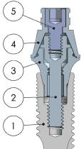
Figure 1. Dental implant-supported prostheses structure: (1) implant; (2) abutment screw; (3) abutment; (4) coping and (5) screw prosthesis.
Table 1. Relevant data on the prosthetic screws analyzed in this work.
Sample # |
Prosthesis |
Connection |
Intermediary |
Place # |
Time |
1 |
Protocol |
HE (3,75) |
Mini pillar |
Jaw (33) |
6 months |
2 |
Protocol |
HE (3,75) |
Mini pillar |
Maxilla (21) |
6 months |
3 (fractured) |
Protocol |
HE (3,75) |
Mini pillar |
Jaw (33) |
1 year |
4 |
Protocol |
HE (3,75) |
Mini pillar |
Jaw (31) |
1 year |
5 |
Protocol |
HE (3,75) |
Mini pillar |
Jaw (41) |
3 years |
6 |
Protocol |
CM (3,75) |
Mini pillar |
Jaw (33) |
5 years |
7 |
Protocol |
CM (3,75) |
Mini pillar |
Jaw (32) |
5 years |
8 (fractured) |
Protocol |
CM (3,75) |
Mini pillar |
Jaw (31) |
5 years |
9 |
Protocol |
CM (3,75) |
Mini pillar |
Jaw (42) |
5 years |
10 |
Protocol |
CM (3,75) |
Mini pillar |
Jaw (43) |
5 years |
11 |
Protocol |
HE (3,75) |
Mini pillar |
Jaw (41) |
5 years |
12 |
Protocol |
HE (3,75) |
Mini pillar |
Maxilla (11) |
5 years |
13 |
Protocol |
HE (3,75) |
Mini pillar |
Jaw (31) |
10 years |
14 |
Unit |
HE (3,75) |
Pillar conic |
Jaw (41) |
20 years |
An important clinical factor was that the majority of the screws were tightened every year or every two years. The time of use varied from 6 months to 20 years. Two fractured screws were removed and analyzed.
All collected screws were analyzed in the electron scanning microscope Field Emission Gun (FEI Quanta FEG 250). The samples were observed with magnification between 50 and 5000x. Before the analysis, the screws were washed in ultrasound with acetone for ten minutes.
Figures 2 to 8 show the surface morphologies of the screws. All of them had defects such as circumferential grooves in the flanks (sidewalls), galling (surface roughness), plastic deformations on the crest (vertex) of the thread and organic material. The circumferential grooves come from the machining process and the preload. The galling is caused by the screw machining process and the friction among parts. The crest deformations are due to contact between the flank of the abutment and the screw threads during tightening and retightening.
A comparison of the morphologies of screws 1 and 2 (Figure 2) shows that there are no significant differences between them after six months of use. Both screws have plastic deformation due the surface friction against the abutment thread.
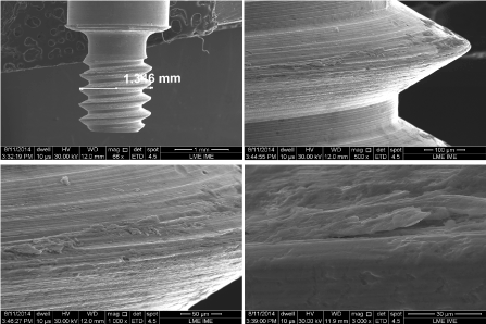
Figure 2. SEM micrographs of screw number 1, removed after six months of use, showing grooves inherited from the machining process and severe plastic deformation of the threads. Same screw of use.
In Figure 3, it is possible to observe that a degradation of the screw occurred, characterized by formation of microcavity into screw surface.
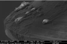
Figure 3. SEM micrographs of screw number 4, removed after one year of use, showing organic material adhered to the surface.
Seven screws collected after 3 years of use presented large plastic deformations of the crest and of the flank (sidewalls) of the threads (Figure 4). On the other hand, five screws did not show significant plastic deformation after 5 years of use (Figure 5).
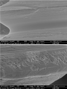
Figure 4. SEM micrographs of screw number 5, removed after three years of use, showing severe plastic deformation, especially in the crest of the threads.
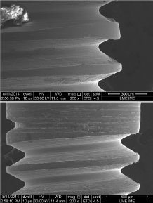
Figure 5. SEM micrographs of screw number 7, removed after five years of use, showing variation of the pitch length caused by plastic deformation, stretch marks on the shank, plastic deformation of the flank and adhered organic material.
The surface grooves of the screws increase the roughness, which increase the surface friction coefficient between the prosthetic retaining screw threads and abutment screw threads. The stress induced by the preload increased the plastic deformation of the screw threads. This seems to be the reason why we observed deep grooves in the first two or three threads, where the coupling force between the parts is larger. It is also noticeable the process of degradation that the screw material undergoes with the time of use (Figures 3 and 4).
Figure 6 shows a representative fracture surface morphology of the two screws. The screw number 3, removed from a prosthesis in the left mandibular canine (position 33) after one year of use, and screw number 8, removed from a prosthesis in the left mandibular central incisor (position 31) after 5 years of use. The crack responsible for the fracture nucleated at root of the threads. The fracture surfaces showed dimples (microcavities) which suggest a ductile fracture. Near the site of crack nucleation, the dimples present plastic deformations due to the compressive stress of opening and closing the cracks. In Figure 6b, one can see a second phase inside the microcavity and striations formed during crack propagation. This is a typical fatigue fracture.
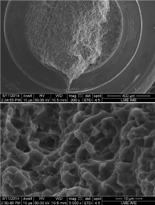
Figure 6. SEM micrographs of the fracture surfaces of screw number 3, removed after one year of use, and screw number 8, removed after five years of use, suggesting a ductile fracture in both cases.
Figure 7 shows the morphology of screw number 13, removed from the mandibular left incisor central (teeth number 31) after 10 years of use, where we can see thread deformation. The screws showed grooves that came from the manufacturing process, which do not compromise the clamping forces between the parts. In Figure 7, one can see a crack due to shear stress by oblique loading on the prosthesis.
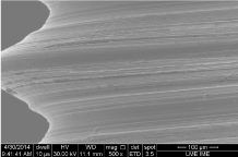
Figure 7. SEM micrographs of screw number 13, removed after ten years of use, showing thread deformation and surface roughening.
Figure 8 shows the surface morphology of screw number 14, removed from tooth number 41 (mandibular right central incisor) after 20 years of use. One can see plastic deformation, organic materials and screw degradation. Microbiological analyses were not made, but the morphology suggests the presence of spaces between screw and implant threads that allowed oral fluid penetration.
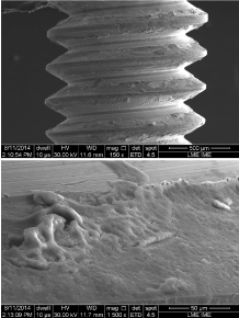
Figure 8. SEM micrographs of screw number 14, removed after twenty years of use.
Several authors [2,10,13] have investigated the loosening of prosthetic screws in “in vitro testing”. The difference between the present work and previous ones is the analysis of prosthetic retaining screws submitted to chewing from 6 months to 20 years. The screws were exposed to oral fluid, axial and non-axial load, and retightening.
It is possible to see that the different morphology of the surface of prosthetic screws can have a significant effect on loosening. Among the causes of screw loosening, the most important ones are: low preloading due an inappropriate torque, vertical discrepancy on the abutment-implant, unfitting between the screw and the implant, cyclic load on several components, the presence of oral fluid that decreases the friction coefficient, and excessive occlusal forces. In general, when a torque is applied to the screw, the wrinkles of the screw thread are flattened.
Large friction coefficient between the couplings of the screw threads may prevent loosening. The applied tightening torque increases the frictional force between the contacting surfaces because of the increased preload.
The stability of the dental implant and prosthetic structure is related to the density of the bone that receives the implant. This may account for the fact that the stability of the structure increases as the bone density increases. Consequently, the screw loosening is more frequent in the case of implants on the upper jaw, which is less dense than the lower jaw.
There are several theories trying to explain the causes of screw loosening, but none of them are conclusive. Everybody agrees that loosening will not happen unless the friction forces between the threads are reduced by some external mechanism. In the present case analyze, the friction between the threads of the prosthetic screw (#5 in Figure 1) and the threads of the abutment screw (# 2 in Figure 1) is proportional to the axial force (preload) that pushes the coping (#4 in Figure 1) against the abutment (#3 in Figure 1). Over time, the screws threads may deform, reducing the normal force responsible for the friction. As a result, it is easier for oral load and vibrations to rotate the screw.
Theoretical analyses suggest that there is usually a linear relationship between the torque applied to the screw and the preload. This relation can be described by an equation proposed by Bickford [14]:

Where, Fp is the preload, T is the torque applied to the screw, p is the screw pitch, µ is the friction coefficient between the screw threads and prosthesis component threads, r is the minor radius of the screw and b is the thread half angle.
According to the equation above, the preload depends on three factors: the applied torque, the screw geometry and the friction coefficient between the screws thread. Since it is very difficult to determine the friction coefficient for all possible cases, a clinical practical solution is to specify a torque, instead a preload, based on empirical data. One the most used clinical device for control the screw tightening is a torque wrench. Torque wrenches have a ±30% uncertainty. Considering that the preload is the most important factor in determining the stability of the prosthetic screw, the professional should frequently calibrate the torque wrench.
Ideally, the torque should apply the maximum preload that will not damage the screw surface. The torque recommended by the manufacturer depends on the material of the screw, the shape of the screw head, the type of thread, the material of the prosthetic component, and the surface finishing of the thread. In the present work the recommended torque is 20 N.cm for abutment screw and 10 N.cm for prosthesis screw.
Even when the correct preload is applied, the coupling force decreases with use, due to stress or material plastic deformation. The minimum torque required to loosen the screw is always lower than the tightening torque. When the preload is applied, 90% of the torque is dissipated as friction between the screw head and the settlement platform. This means that only 10% of the torque is transformed in tension in the prosthetic screw to join the coping and prosthetic component (abutment) set and prevent it from self-loosening when exposed to oral forces [4]. The tightening torque applied to a screw is absorbed in three ways. First, there is the friction of the prosthetic screw head against the coping, which may absorb 50 percent or more of the total torque. Friction of the prosthetic screw threads against the prosthetic component screw threads absorbs as much as 40% of the applied torque. The final 10% of the applied torque develops the clamping force that holds the coping and prosthetic component together. This means that an increase of only 5% in either friction component may reduce by half the screw tension and preload [14].
Some authors suggest applying a torque larger than the value recommended by the manufacturer as a means to avoid loosening. This practice is not advisable because the preload should be limited to 80% of the tensile yield strength of the material in order to avoid screw strain and fracture during loading [5]. On the other hand, torques lower than the value recommended by the manufacturer may cause early loosening of the screw during masticatory function.
Other authors suggest the application of a second torque some minutes after preloading [5]. This procedure is justified because there is 2% reduction of the preload in the first five minutes after the first torque is applied.
In order to, increase the screw preload without having to increase the tightening torque some dental implant manufacturer altered the prosthetic screw finishing surface, adding a solid lubricant (Teflon) to decrease the coefficient of friction. The manufacturers report that these screws reduce loosening by generation of higher preload values than those produced by traditional prosthetic screws. As the role of the friction coefficient is also somewhat conflicting: on one hand, a low friction coefficient generates a higher preload for a given tightening torque; on the other hand, a low friction coefficient result in lower frictional forces opposing the opening torque.
When the screws evaluated in this work were visually inspected, all of them seemed to be in good condition. However, SEM micrographs revealed the presence of corrosion, biofilm adherence, and plastic deformations. There are no data in the literature about the possibility of reusing a loosened screw. There was not a strong correlation between the adherence of organic material and the usage time.
The internal threads of the implant, prosthetic component and coping may become contaminated with blood, peri-implant fluids, and saliva during the surgery and prosthetic stages. Those contaminants act as lubricants and contribute significantly to loosening of the screw [15].
The presence of some manufacturing flaws can be seen in the surface of some screws (Figures 1B and 5C), but this seems not to be an important factor on the screw stability.
The results of this work show that, after six months of use, the screws exhibited plastic deformation. This result confirms earlier reports by other authors who saw dimensional changes in screws put through torque [15].
Considering the plastic deformations observed in the screws (Figures 2, 5 and 7), it is noticeable that they occurred in areas in which there was more contact between the prosthetic screw threads and the internal abutment screw threads. Deformations are related to the progressive loss of preload with time of use [4], which is the main reason of screw loosening. However, as observed in the present work, these deformations are not the only cause of preload loss. Material degradation, corrosion, and organic material adherence also contribute to the screw loosening.
In some screw surfaces, one can see the deformation of grooves inherited from the machining process, leading to a smoother surface and thus reducing the friction coefficient. Other authors also found the same morphological changes after a number of tightening cycles and concluded that after ten cycles of insertion, a new screw should be used in order to achieve the recommended preload [15,16].
The surface grooves of the screw vary with the manufacturing process, the quality control, and the screw material. The two main manufacturing processes are lamination and machining. Lamination uses compression and plastic deformation, is faster and produces screws with a smoother surface and high mechanical strength due to cold work hardening. Machining is slower and the surface of the material has irregularities from the cutting tools. The quality of finishing depends on the material. The screw alloys Co-Cr and stainless steel are easily handled and the finishing is good. The machining of titanium alloy is harder because it is a material with hexagonal crystal structure, and the finishing is worse.
Friction is fundamental to keep the screw in place after insertion and preload. Tightening and untightening cycles reduce the friction coefficient of the screw head, threads and other components of the set, and, as a consequence, facilitate loosening of the screw. Therefore, the prosthetic screw used by the technician in laboratory procedures should not be sent to the clinic and used for prosthesis fixation. In fact, high torque values to untighten the screw were obtained only for the first ten tightening cycles [15]. When as little as six tightening are made, there is 10% of reduction of the coupling force between the parts [10].
Although it is not usual, prosthetic screws can fracture due to intrinsic properties of the metal alloy, such as hardness, corrosion resistance and fatigue life. However, the main causes of fracture are related to human factors such as installing prostheses with no passivity, bad adaptation of the components and incorrect use of the torque wrench. In the present work, screw fracture (Figure 6) occurred because the prosthetic retaining screws loosened, the patient did not ask for retightening and movement of the prosthesis led to screw overload.
Based on the results of the present work and considering the limitations of this study, we come to the following conclusions:
- In the SEM micrographs, grooves were observed on the screw surfaces that contributed to loosening and possibly compromised prosthetic rehabilitation;
- The prosthetic screws exhibited plastic deformation after tightening, retightening, and long-term use;
- Loosening of the screw is due to plastic deformation and other process that occur during usage, such as corrosion, material degradation, and adherence of organic material;
- It is hard for the clinician to identify defects and plastic deformation in the screw due to retightening and long-term use.
- Goiato MC, dos Santos DM, Santiago JF Jr, Moreno A, Pellizzer EP (2014) Longevity of dental implants in type IV bone: a systematic review. Int J Oral Maxillofac Surg 43: 1108-1116. [Crossref]
- Siamos G, Winkler S, Boberick KG (2002) The relationship between implant preload and screw loosening on implant-supported prostheses. J Oral Implantol 28: 67-73. [Crossref]
- Al Jabbari YS, Fournelle R, Ziebert G, Toth J, Iacopino AM (2008) Mechanical behavior and failure analysis of prosthetic retaining screws after long-term use in vivo. Part3: preload and tensile fracture load testing. J Prosthodont 17: 192-200. [Crossref]
- Saboury A, Asli HN, Vaziri S (2012) The effect of repeated torque in small diameter implants with machined and premachined abutments. Clin Implant Dentistry Rel Res 14: e224-e230. [Crossref]
- Butignon LE, Basilio Mde A, Pereira Rde P, Arioli Filho JN (2013) Influence of three types of abutments on preload values before and after cyclic loading with structural analysis by scanning electron microscopy. Int J Oral Maxillofac Implants 28: e161-e170. [Crossref]
- Stüker RA, Teixeira ER, Beck JC, da Costa NP (2008) Preload and torque removal evaluation of three different abutment screws for single standing implant restorations. J Appl Oral Sci 16: 55-58. [Crossref]
- Cerutti-Kopplin D, Rodrigues Neto DJ, Valle AL, Pereira JP (2014) Influence of reverse torque values in abutments with or without internal hexagon indexes. J Prosthet Dent 112: 824-827. [Crossref]
- Hirata R, Machado LS, Bonfante EA, Yamaguchi S, Imazato S, et al. (2015) Effect of Diamond like Carbon Coating on Reliability of Implant-Supported Crowns. Int J Oral Maxillofac Implants 30: 806-813. [Crossref]
- Bozkaya D, Müftü S (2005) Mechanics of the taper integrated screwed-in (TIS) abutments used in dental implants. J Biomech 38: 87-97. [Crossref]
- Martin WC, Woody RD, Miller BH, Miller AW (2001) Implant abutment screw rotations and preloads for four different screw materials and surfaces. J Prosthet Dent 86: 24-32. [Crossref]
- Elias CN, Figueira DC, Rios PR (2006) Influence of the coating material on the loosing of dental implant abutment screw joints. Mater Sci Eng C 26: 1361-1366.
- Park CI, Choe HC, Chung CH (2004) Effects of surface coating on the screw loosening of dental abutment screws. Metals Mat Int 10: 549-553.
- Williamson RT, Robinson FG (2001) Retrieval technique for fractured implant screws. J Prosthet Dent 86: 549-550. [Crossref]
- Kano SC, Binon P, Bonfante G, Curtis DA (2006) Effect of casting procedures on screw loosening in UCLA-type abutments. J Prosthodont 15: 77-81. [Crossref]
- Bickford JH (2008) Introduction to the design and behavior of bolted joints. CRC Press, p140.
- Guzaitis KL, Knoernschild KL, Viana MAG (2011) Effect of repeated screw joint closing and opening cycles on implant prosthetic screw reverse torque and implant and screw thread morphology. J Prosthet Dent 106: 159-169. [Crossref]


