Coronary artery perforations (CAP) are rare but known complications during percutaneous coronary intervention (PCI). We present two cases demonstrating the novel “Self-Made Covered Stent” technique for managing CAP. The technique involves creating a controlled dissection flap, which is then tacked down with a stent to seal the CAP.
coronary perforation, covered stent, complications
Iatrogenic coronary artery perforation (CAP) during percutaneous coronary intervention (PCI) is a rare but known complication, which occurs when a dissection or intimal tear penetrates the arterial wall leading to extravasation of blood beyond the layers of the arterial wall [1]. A variety of different modalities exist to treat CAP, including the use of beads, coils, thrombin, and other sealant material, but these treatments will terminate flow to the distal vascular bed. Balloon tamponade is an effective strategy in order to maintain distal vessel flow, but it may fail to completely seal the perforation. Covered stents, on the other hand, are significantly more effective in sealing CAP than balloon tamponade alone but have significantly higher in-stent thrombosis and restenosis rate (up to 6% and 30% at 6 months, respectively), given that they are covered with the biocompatible polymer polytetrafluoroethylene (PTFE) or polyurethane [2,3]. Furthermore, in calcified and tortuous vessels, covered stents may be difficult to deliver and/or expand. Herein, we describe a novel technique – called the Self-Made Covered Stent – in which a controlled dissection flap is made to cover a perforation and tacked down with a conventional non-covered stent (Figure 1). It affords the benefits of a covered stent without many of the drawbacks.
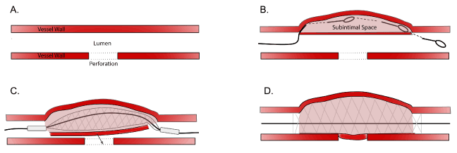
Figure 1. Self-made Covered Stent Technique
Panel A. Coronary vessel with a perforation (depicted with dashed lines)
Panel B. Use of a hydrophilic jacketed wire to knuckle into the subintimal space, create a dissection flap, and re-enter back into the true lumen distally
Panel C. Placement of a stent within the subintimal space to push dissection flap to cover the perforation (arrow shows the dissection flap being pushed to cover the perforation)
Panel D. Deployment of the stent to seal the perforation
A 68-year old female with hypertension, hyperlipidemia, and type 2 diabetes mellitus developed Canadian Cardiovascular Society (CCS) class III angina for which she underwent a pharmacologic stress test. The study demonstrated severe anterior wall ischemia with follow-up coronary angiography revealing a 99% ostial, calcific left anterior descending artery (LAD) (Figure 2, Panel A). The patient opted for percutaneous coronary intervention (PCI) of the lesion. A 7Fr JL4 guide catheter from the right femoral artery was utilized for the PCI. Standard workhorse wires were tried but were unable to cross the lesion. A Whisper wire (Abbott Vascular, Santa Clara, CA) was then used but it went subintimal near the lesion (Figure 2, Panel B). A Corsair microcatheter (Asahi Intecc, Nagoya, Japan) was placed over the wire with the plan to perform antegrade dissection re-entry. The Whisper wire was exchanged for a Gaia 2nd (Asahi Intecc) through the microcatheter. However, the wire exited the vessel and the microcatheter was advanced over the wire before the wire exit was realized. An injection through the microcatheter demonstrated that it was in the pericardium (Figure 2, Panel C). The system was left in place to tamponade the bleeding, and a second system with a Finecross microcatheter (Terumo, Tokyo, Japan) with a Fielder XT (Asahi Intecc) was then intentionally wedged proximal to the dissection and used to facilitate subintimal wire passage proximal to the perforation via a mini-STAR technique [4]. A knuckle formed and it was advanced forward to form a dissection flap. The knuckled wire was pushed until it exited into the true lumen of the distal LAD (Figure 2, Panel D). The Finecross microcatheter was advanced forward and the Fielder XT was switched out for a standard workhorse wire. The extravascular Turnpike microcatheter was then removed and the LAD was stented over the workhorse wire in the distal LAD using intravascular ultrasound (IVUS). Final angiography demonstrated no residual perforation (Figure 2, Panel E).
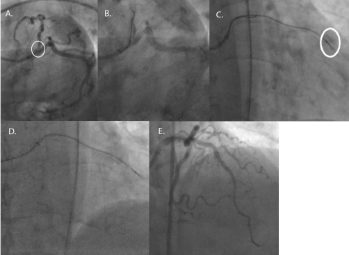
Figure 2. LAD PCI – Wire Re-entry
Panel A. Angiography revealing a proximal LAD lesion. (Circle denotes the proximal LAD lesion.)
Panel B. Hydrophilic wire in the subintimal space.
Panel C. Microcatheter in the pericardium. (Circle denotes the perforation.)
Panel D. Fielder XT pushed forward in the subintimal spaced and re-entered in the distal LAD.
Panel E. Final result with no perforation.
A 59-year old male with a 30-pack year smoking history, hypertension, and hyperlipidemia developed CCS III angina over 6 months. After his angina failed to improve with three anti-anginal, he was referred for coronary angiography, which demonstrated a distal right coronary artery (RCA) chronic total occlusion (CTO) with no other significant disease. Given the ongoing nature of his symptoms, the decision was made to proceed with RCA CTO PCI. Using bi-radial access, a 7Fr AL1 and 7Fr EBU 3.5 were used for dual angiography (Figure 3, Panel A). An antegrade approach using wire escalation was utilized to cross the CTO. A workhorse wire with a 2.0 mm compliant balloon in a marginal branch was also used to anchor the antegrade guide. A Turnpike microcatheter (Vascular Solutions, Minneapolis, MN) with a Gaia 2nd wire (Asahi Intecc) was used to puncture the proximal cap of the CTO but it led to a wire exit in the distal vessel (Figure 3, Panel B). An antegrade injection demonstrated an Ellis type III perforation (Figure 3, Panel C). In this case, the microcatheter was then pulled back and the Gaia 2nd wire was exchanged for a Fielder XT. The Fielder XT went subintimal proximal to the dissection, and the knuckled wire was pushed forward into the distal vessel to create a dissection flap (Figure 3, Panel D). Once confirmation of the wire location within the body of the vessel was obtained in multiple orthogonal views, it was switched back for a Gaia 2nd wire, which was re-directed to enter the true lumen (Figure 3, Panel E). Using IVUS-guidance, the RCA was stented distally to proximally with final angiogram demonstrating no residual perforation (Figure 3, Panel F).
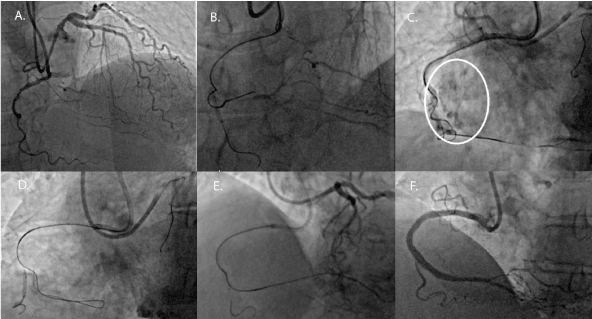
Figure 3. RCA CTO PCI – Wire Re-entry
Panel A. Dual angiography demonstrating a distal RCA CTO.
Panel B. Guidewire exit which resulted in a perforation.
Panel C. Perforation in the distal RCA. (Circle denotes the perforation.)
Panel D. Fielder XT guidewire in the subintimal space with a knuckle.
Panel E. Gaia 2nd wire in the distal true lumen as confirmed by a retrograde injection.
Panel F. Final result with no perforation.
To the best of our knowledge, this is the first description of creating a controlled dissection flap to seal a perforation. In essence, our technique mimics the advantages of covered stents while circumventing their major drawbacks. Covered stents have been traditionally used as bail‐out treatment of CAP, especially when located in proximal or mid-vessel segments. The primary function of a covered stent is to seal the perforation with a layer impervious to blood. Our technique uses the dissection flap, in lieu of the PTFE or polyurethane, to seal the perforation, which theoretically should not incite the same neointimal response as a covered stent. Moreover, in calcified and tortuous vessels, it may be arduous to deliver a covered stent through the vessel's lumen due to the bulkiness and lack of flexibility of the stent. Our technique obviates that issue by allowing for the use of a standard drug-eluting or bare metal stent for delivery. It should be noted that the technique described does have some limitations. The vessel size of the perforated vessel must be large enough to accommodate a stent. Therefore, it is not appropriate for distal CAP in small caliber vessels. The technique also requires that the operator be able to enter the subintimal space, create a controlled dissection, and re-enter into the true lumen (all while managing a perforation from the initial wire passage). As a result, this technique is challenging and may not be applicable to all interventionalists. Moreover, if the dissection is not appropriately created and controlled, it can lead to abrupt vessel closure and/or worsening of the existing perforation. Lastly, the technique may not be suitable for unstable patients with large hemodynamically compromising perforations.
No funding was involved in the writing of this manuscript.
D.D. is on the speaker’s bureau for Abbott Vascular, Boston Scientific, and Medtronic and has research support from Biotronik. N.J.L. reports consulting fees from Abbott Vascular, Abiomed, Boston Scientific, and Medtronic. D.K. is on the speaker’s bureau of Abbott Vascular, Abiomed, and Boston Scientific and has equity in Soundbite, Saranas, and Traverse Vascular. All other authors have nothing to disclose.
- Ellis SG, Ajluni S, Arnold AZ, Popma JJ, Bittl JA, et al. (1994) Increased coronary perforation in the new device era. Incidence, classification, management, and outcome. Circulation 90: 2725-2730. [PubMed]
- Gercken U, Lansky AJ, Buellesfeld L, Desai K, Badereldin M, et al. (2002) Results of the Jostent coronary stent graft implantation in various clinical settings: procedural and follow-up results. Catheter Cardiovasc Interv 56: 353-360. [PubMed]
- Lansky AJ, Yang YM, Khan Y, Costa RA, Pietras C, et al. (2006) Treatment of coronary artery perforations complicating percutaneous coronary intervention with a polytetrafluoroethylene-covered stent graft. Am J Cardiol 98: 370-374. [PubMed]
- Galassi AR, Tomasello SD, Costanzo L, Campisano MB, Barrano G, et al. (2012) Mini-STAR as bail-out strategy for percutaneous coronary intervention of chronic total occlusion. Catheter Cardiovasc Interv 79: 30-40. [PubMed]