Abstract
We designed a valved hybrid fractal stent for treatment of unruptured cerebral aneurysms. The stent has a coil catheter insertion hole and is formed in a fractal pattern. The fractal pattern uses a flow-diverter effect to direct blood flow into a cerebral aneurysm. Using computational fluid dynamics (CFD) simulation, blood flow velocity in the cerebral aneurysm was evaluated. In addition, structural analysis was used to evaluate opening of the valve mechanism by the coil catheter. We succeeded in suppressing flow velocity in the aneurysm using the valved hybrid fractal stent and were able to open the valve mechanism with the catheter.
Keywords
Cerebral aneurysm, Stent, Coil embolization, Flow diverter, Computational Fluid Dynamics, Structural Analysis
Introduction
This study aims to develop a new therapeutic device for the treatment of unruptured cerebral aneurysms. According to the World Health Organization, the leading causes of death in 2012 were ischemic heart disease, cerebrovascular disease, chronic obstructive pulmonary disease, lower respiratory tract infections, and bronchitis, in descending order of frequency.[A1] Cerebrovascular disease is characterized as obstructive, in which blood vessels are occluded by thrombus or stenosis, and hemorrhagic, with intracranial bleeding [1]. A cerebral aneurysm results from degenerative changes in the arterial wall. If the aneurysm ruptures, the patient may die due to subarachnoid hemorrhage.
There are two treatment approaches for cerebral aneurysms: craniotomy and endovascular [A2] therapy. Craniotomy is used to close the entrance of a cerebral aneurysm with metallic clips to prevent inflow of blood. However, this method has a high risk of complications, and long-term hospitalization may result [2-5]. There are two minimally invasive treatment methods. In coil embolization, the surgeon inserts a micro catheter through a blood vessel in the groin or wrist to reach the lesion. A flexible wire made of platinum is then placed in the catheter, and it fills the coil. Even deep brain lesions can be treated without technical difficulty, but treatment of an aneurysmal dome with a wide neck using coils may be problematic, with a risk of thrombus formation and leakage in the parent vessel. Another option is stent placement, for use in an aneurysm with a wide neck. The stent acts as a flow diverter in the vessel lumen to prevent blood flow into the aneurysm. Flow-diverter stents are in clinical use in Europe, Japan and the USA. In the previous study, we researched the stent and catheter for hybrid [6-8]. By placing the flow-diverter stent in the neck of the dome, blood flow into the aneurysm is suppressed. This promotes thrombosis in the dome and reduces the risk of rupture. This procedure is similar to coil embolization in its low invasiveness [9-12]. However, deaths cases have occurred with stent placement [13-16]. Therefore, development of an improved therapeutic device for unruptured cerebral aneurysms is desirable.
In this research, we designed a valved hybrid fractal stent as a new endovascular device for minimally invasive treatment of unruptured cerebral aneurysms. We verified functionality by performing structural and numerical fluid analysis on stent models
Valved Hybrid Fractal Stent
Hybrid Fractal Stent
A fractal stent is used to solve problems associated with coil embolization and stent surgery [17-22]. Figure 1[A3] shows a hybrid fractal stent with a flow-diverter effect. When the flow-diverter effect is inadequate, it is still possible to prevent flow of blood into the cerebral aneurysm by performing coil embolization through the catheter insertion hole. [A4] Figure 1 shows the shape of a fractal stent. The stent has a flow-diverter effect and can suppress flow of blood into a cerebral aneurysm.
Figure 1. Overall view of the Hybrid Fractal Stent.
The flow diverter effect is the effect of controlling and diverting the flow of fluid. By this effect, the amount of blood flowing into the cerebral aneurysm from the blood vessel can be suppressed. [A5] A fractal stent has a shape different from that of a mesh-pattern conventional stent. In a conventional stent, the mesh is roughly in the form of a lattice. However, the mesh in the hybrid stent has a fractal structure, meaning that the whole and part of the structure are self-similar. The hybrid stent achieves a flow-diverter effect through its fractal structure [23-25].
The effect of the fractal stent is based on the following. First, the use of a fractal structure increases its surface area, making population by vascular endothelial cells easier. Second, the influx of blood into an aneurysm can be suppressed by the flow-diverter effect. Third, coil therapy can be performed through the catheter insertion hole when the influx is not sufficiently inhibited by the flow-diverter effect. An advantage of a fractal stent is that that coil embolization can be performed even after stent placement.
A problem with the fractal stent is that its function may not be easily determined, because the coil for catheter insertion is always open, allowing blood flow.
The valve-attached hybrid fractal stent is a stent newly proposed to solve the problem of the above-described hybrid fractal stent. The valve-attached hybrid fractal stent has a fractal pattern in the catheter insertion hole of the coil of the hybrid fractal stent, and it is a hybrid stent of a fractal stent and a valved stent.
Stent Design
Figure 3 shows the shape of a silk flow-diverter stent (Balt Extrusion, Memorency, France). We show previously studied fractal stents, as well as proposed and valved hybrid fractal stents (Fig[A6] ure 4-15). Fractals A and B were proposed by Kojima et al. ,and Fractal-E was proposed by Ichikawa et al. [22-23]. Regardless of the presence or absence of a valve mechanism, the fractal stent is provided with a coil catheter insertion hole. For Fractal-G, H with no valve mechanism as O, one with valve mechanism as V. [A7] For fractals I and J, we proposed two models of different thickness (t = 30 or 50 μm). In fractals G, H, I, and J, fluid simulation was carried out for two installation angles of 0° and 45°. Those with an installation angle of 45° are labelled "slant".
Figure 2: The valved hybrid fractal stent model. (a)Valved Hybrid Fractal Stent Sheet. (b) Behavior of valve mechanism
Figure 3. Silk
Fluid Analysis of Stent
Numerical fluid analysis was performed using Autodesk [A8] software (Autodesk® CFD 2016) to evaluate the effect of conventional and newly-proposed stents. Autodesk® CFD 2016 is a numerical fluid analysis software program that simulates numerical fluid dynamics using a model made with 3D-CAD. The model analyzed should be a non-detention model (Control) and all the 24 stented indented stents shown in Chapter 2, Section 3.[A9]
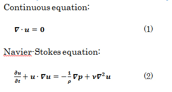
Basic equations for numerical fluid analysis
Evaluation Process
First, we obtain velocity data at arbitrary points in the aneurysm as shown in figure 16. In this simulation, observations are made at a total of 193 points in the nodule [A10] set at 0.5-mm intervals.
Figure 4. Fractal-A
Figure 5. Fractal-B
Figure 6. Fractal-C
Figure 7. Fractal-D
Figure 8. Fractal-E
Figure 9. Fractal-F
Figure 10. Fractal-G_O. (a) Installation angle: 0°, (b)slant (Installation angle: 45°).
Figure 11. Fractal-G_V. (a) Installation angle 0°, (b)slant (Installation angle 45°).
Figure 12. Fractal-H_O.
Figure 13. Fractal-H_V. (a) Installation angle: 0°, (b)slant(Installation angle: 45°).
Figure 14. Fractal-I. (a) Installation angle: 0°, (b)slant (Installation angle: 45°).
Figure 15. Fractal-J. (a) Installation angle: 0°, (b)slant(Installation angle: 45°).
Figure 16. Observation points.
Next, the root mean square (RMS) at each time point is calculated.
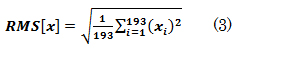
Finally, we compare the RMS values for each stent model and evaluate the inhibitory effect on blood flow into the cerebral aneurysm.
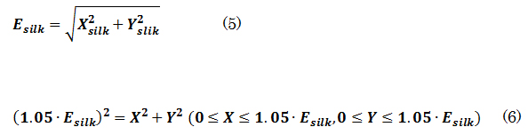
The correlation between suppression of blood flow velocity in the nodule and the coverage of the stent when implanted, vs. that in the Control model, is shown. The coverage was calculated based on the area occupied by the stent strut (10 mm2) using the following formula

Boundary condition
Figure 17 shows the flow-path model. An aneurysm occurs in a curved parent vessel with an inner diameter of 4 mm. Each stent model is placed in the neck of the flow-path model.
Figure 17. Flow path model.
Initial conditions are 0 mm/s flow rate and 0 mmHg pressure for both inlet and outlet.
In the boundary condition, we set the pulsatile flow average value of blood flow measurements at the vessel inlet of 7 patients with magnetic resonance angiography data (Kojima et al., 2012) [7]. Figure 18 shows the waveform of pulsatile flow.
Figure 18. Boundary condition at the inlet.
Assuming that the working fluid is blood, the density is 1,050 [kg/m3], the viscosity is 3.47 × 10⁻³ [Pa · s]. In this calculation, we analyzed the flow of the affected part as incompressible, turbulent, and in an unsteady state.
Results of analysis
Figure 19 shows the relationship between the magnitude of the speed at the time of implantation of each stent model and the coverage rate of the stent model, vs. that in the Control. The red dashed line in figure 19 is represented by formula (6), which shows the correlation between speed and coverage in silk + 5%.
Figure 19. Correlation between the speed magnitude for Control and the coverage ratio.
A, B, G_V_slant, H_V_slant, I (t = 50 μm), J (t = 30, 50 μm) are obtained from the expectation of flexibility and flexibility due to the magnitude of speed and low coverage has the same effect.[A11]
Discussion
The influence on flow-velocity suppression due to the difference in installation angle for the same pattern was examined. Figure 20 shows the flow vector just above the stent in J and J_slant (both t = 50 μm). It can be seen that flow going toward the inspection plane occurs in J. This is thought to be caused by a large number of struts intersecting at an angle when the blood flow passes through the stent, with respect to the inside of the coil insertion hole. On the other hand, J_slant shows that the blood flow in the parent vessel and the flow after passing through the stent are minimally changed. This is thought to be because the flow-diverter effect is weakened as the blood passes through the stent in the coil insertion hole, since many struts are parallel to the blood flow path. Comparing the two stents, it seems that modified flow as in J occurs; the stents collide with each other on the examination plane, so that a large deceleration effect can be achieved. Therefore, in determining the stent pattern, control of blood flow with a flow-diverter effect can be realized by designing the density and arrangement of the struts to intersect at an angle to the flow of the parent vessel.
Figure 20. Flow vectors directly above the stent (a)J (t=50μm), (b)J_slant (t=50μm).
Experiment
With respect to the t = 30-mm model Type J, which sufficiently suppressed flow in both fluid and structural analysis, and which can accept insertion of a coil catheter, the fractal effect and the flow-reduction depend on the direction of the pattern-induced flow. [A12] To verify this effect, a fluid observation experiment was carried out using particle image velocimetry (PIV). In the experiment, we used a 5-fold model based on observation, and adjusted the flow rate to 1/5 of that rate.
In the fractal model, a 5-fold body was created with a 3D printer (Design Jet[A13] ) (Figure 21). Polyvinyl alcohol (PVA) was used as a printer material. Compared to metals, the strength is poor, but PVA does not deform with flow, and experiments are possible. Likewise, a 5-fold body was prepared for an aneurysm model (Figure 22). This was done by creating a model with a 3D printer using acrylonitrile butadiene styrene (ABS) resin, shaping it with polydimethylsiloxane (PDMS), curing it with PDMS, and melting the ABS model with acetone[A14] . The aneurysm was separated from the blood vessel, the fractal sheet in figure 21 was sandwiched there between [A15] and fixed with a jig. As PDMS has flexibility, it is possible to sandwich a sheet of fractal stent and allow fluid to flow without causing leakage by pinching with a jig. The experimental results are shown in figure 24. Analysis of PIV, the flow has occurred as a whole in the case where there is no stent using Flownizer (Detect Inc.). In the case with a stent with a pattern diagonal to flow (b) and vertically level (c), as in the above discussion, [A16] the flow rate decreases for objects with diagonal patterns. The average flow velocity in the aneurysm is shown below.
Figure 21. Fractal stent type J (t = 30μm) 5 times model.
Figure 22. Aneurysm Model 5 times model.
Figure 23. Experimental setup of PIV.
Figure 24. Experimental result of PIV.
-No stent 7.5 [mm/s]
-With stent angle 0°, 3.1 [mm/s], 41% without stent
-With stent angle 90° 3.8 [mm/s], 51% without stent
Analysis showed that a stent angle of 0° degree was 27% compared with without the stent and the stented angle 90º was 40%. [A17] Although the absolute speed is different from these analytical results, the experimental results showed that the installation resistance is larger when the installation angle is 0° when the installation angle is 0 ° and 90 °, the structure is oblique to the flow it was done[A18] .
Conclusion
A hybrid fractal stent was proposed as a new flow-diverter that can be used in conjunction with coil embolization. CFD simulation verified the effect of suppressing flow velocity on blood flow in a cerebral aneurysm during stent placement. Based on the simulation results, the flow-rate suppression was comparable to that of the silk stent clinically used in fractals G_V_slant, H_V_slant, I, J (t = 30, 50 μm) among the models proposed.
Based on the simulation results, fractals I (t = 30 μm) and J (t = 30 μm) among the models proposed showed an opening allowing insertion of a coil catheter (φ = 3 Fr = 1 mm). Experiments with type J (t = 30 m) showed that when the installation angle was changed, even when the pattern was oblique to the flow even if it was the same pattern, when the pattern was horizontal and vertical, the fluid resistance worked more obliquely It was confirmed.[A19]
It was confirmed that the proposed hybrid fractal stent is feasible as a therapeutic device for use in cerebral aneurysms. The differences in flow rate suppression among models are unknown, and further investigating is required. In this study, fluid analysis was performed under the condition of general pulsatile flow, but the effects should be verified under special pulsatile flow. In addition, we will prepare a cylindrical stent to verify the fluid experiment, and create a stent containing the necessary folding mechanism.
References
- Armoiry X, Paysant M, Hartmann D, Aulagner G, Turjman F (2012) Interest of flow diversion prostheses in the management of unruptured intracranial aneurysms. Int J Vasc Med 2012: 654627. [Crossref]
- Benndorf G, Herbon U, Sollmann WP, Campi A (2001) Treatment of a ruptured dissecting vertebral artery aneurysm with double stent placement: case report. Am. J. Neuroradiol. 22: 1844–1848. [Crossref]
- Doerfler A, Wanke I, Egelhof T, Stolke D, Forsting M (2004) Double-stent method: therapeutic alternative for small wide-necked aneurysms. Technical note. J Neurosurg 100: 150-154. [Crossref]
- Hurst D, Vassilicos JC (2007) Scalings and decay of fractal-generated turbulence. Phys. Fluids 19: 035103.
- Kim YH, Xu X, Lee JS (2010) The effect of stent porosity and strut shape on saccular aneurysm and its numerical analysis with lattice Boltzmann method. Ann Biomed Eng 38: 2274-2292. [Crossref]
- Kojima M, Irie K, Fukuda T, Arai F, Hirose Y, et al. (2012) The study of flow diversion effects on aneurysm using multiple enterprise stents and two flow diverters. Asian J Neurosurg 7: 159-165. [Crossref]
- Masahiro Kojima, Keiko Irie, Seiichi Ikeda, Toshio Fukuda, Fumihito Arai, et al. (2012) The Hemodynamic Study for Growth Factor Evaluation of Rupture Cerebral Aneurysm Followed up for Five Years. J. Biomed. Sci. Eng. 5: 884-891.
- Ku DN, Giddens DP, Zarins CK, Glagov S (1985) Pulsatile flow and atherosclerosis in the human carotid bifurcation. Positive correlation between plaque location and low oscillating shear stress. Arteriosclerosis 5: 293-302. [Crossref]
- Lubicz B, Collignon L, Raphaeli G, Pruvo JP, Bruneau M, et al. (2010) Flowdiverter stent for the endovascular treatment of intracranial aneurysms a prospective study in 29 patients with 34 aneurysms. Stroke 41: 2247-2253. [Crossref]
- Lylyk P, Cohen JE, Ceratto R, Ferrario A, Miranda C (2002) Endovascular reconstruction of intracranial arteries by stent placement and combined techniques. J Neurosurg 97: 1306-1313. [Crossref]
- Lylyk P, Miranda C, Ceratto R, Ferrario A, Scrivano E. et al. (2009) Curative endovascular reconstruction of cerebral aneurysms with the pipeline embolization device: the buenos aires experience. Neurosurgery. 64: 632-643. [Crossref]
- Malek AM, Alper SL, Izumo S (1999) Hemodynamic shear stress and its role in atherosclerosis. JAMA 282: 2035-2042. [Crossref]
- Mantha A, Karmonik C, Benndorf G, Strother C, Metcalfe R (2006) Hemodynamics in a cerebral artery before and after the formation of an aneurysm. AJNR Am J Neuroradiol 27: 1113-1118. [Crossref]
- Mehta B, Burke T, Kole M, Bydon A, Seyfried D, et al. (2003) Stent-within-a-stent technique for the treatment of dissecting vertebral artery aneurysms. AJNR Am J Neuroradiol 24: 1814-1818. [Crossref]
- Meng H1, Wang Z, Hoi Y, Gao L, Metaxa E, et al. (2007) Complex hemodynamics at the apex of an arterial bifurcation induces vascular remo- deling resembling cerebral aneurysm initiation. Stroke 38: 1924-1931. [Crossref]
- Kouji Nagata, Yasuhiko Sakai, Takuto Inaba, Hiroki Suzuki, Osamu Terashima, et al. (2013) Turbulence structure and turbulence kinetic energy transport in multiscale/fractal-generated turbulence. Phys. Fluids 25: 065102.
- Nelson PK, Lylyk P, Szikora I, Wetzel SG, Wanke I, et al. (2011) The pipeline embolization device for the intracranial treatment of aneurysms trial. AJNR Am J Neuroradiol 32: 34-40. [Crossref]
- Seoud RE, Vassilicos JC (2007) Dissipation and decay of fractal-generated turbulence. Phys. Fluids 19: 105108.
- Shimogonya Y, Ishikawa T, Imai Y, Matsuki N, Yamaguchi T (2009) Can temporal fluctuation in spatial wall shear stress gradient initiate a cerebral aneurysm? A proposed novel hemodynamic index, the gradient oscil- latory number (GON). J. Biomech. 42: 550-554. [Crossref]
- Szikora I, Berentei Z, Kulcsar Z, Marosfoi M, Vajda ZS, et al. (2010) Treatment of intracranial aneurysms by functional reconstruction of the parent artery: the budapest experience with the pipeline embolization device. Am. J. Neuroradiol. 31: 1139-1147. [Crossref]
- Vanninen R, Manninen H, Ronkainen A (2003) Broad-based intracranial aneurysms: thrombosis induced by stent placement. AJNR Am J Neuroradiol 24: 263-266. [Crossref]
- Ichikawa Akihiko, Ito Takahiro, Shimokigaki Kohei, Kubo Taka, Fukuda Toshio (2015) Study of a hybrid fractal stent with valves for next generation cerebral endovascular treatment. Proceedings of the Japan Society of Mechanical Engineers, The Japan Society of Mechanical Engineers 81.
- Masahiro Kojima, Keiko Irie, Kouhei Masunaga, Yasuhiko Sakai, Masahiro Nakajima, et al. (2016) Hybrid stent device of flow-diverting effect and stent-assisted coil embolization formed by fractal structure. Medical & Biological Engineering & Computing, 54: 831-841.