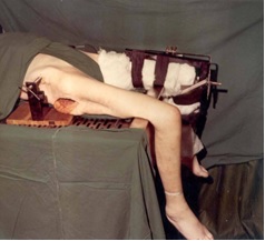
Figure 1. Device used to test stability of the Hip Joint showing the pelvis fixed and protractors to measure the angle of flexion/extension, adduction/abduction and internal rotation/external rotations (Courtesy: Photograph reproduced with the kind permission of Injury/Elsevier).
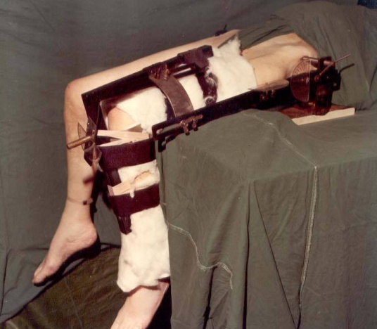
Figure 2. Device used to test stability of the Hip Joint showing the pelvis fixed and protractors to measure the angle of flexion/extension, adduction/abduction and internal rotation/external srotations (Courtesy: Photograph reproduced with the kind permission of Injury/Elsevier).
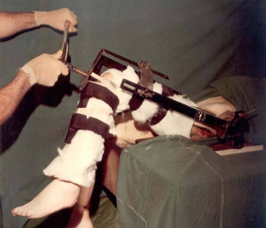
Figure 3. . Internal rotation torque being applied when the Hip Joint is standardized to a fixed angle of flexion and adduction (Courtesy: Photograph reproduced with the kind permission of Injury/Elsevier).
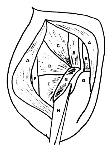
Figure 4. Line Diagram showing the osteotomy of the posterior overhanging part of the greater trochanter: (Courtesy: Line Diagram reproduced with the kind permission of Injury/Elsevier): A: Gluteus maximus; B: Gluteus medius; C: Piriformis; D: Triradiate tendon; E: Quadratus femoris; F: Sciatic nerve; G: Greater trochanter, H: Osteotome.
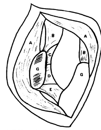
Figure 5. Line Diagram showing the osteotomy completed and the flap retracted. (Courtesy: Line Diagram reproduced with the kind permission of Injury/Elsevier); A: Gluteus maximus; B: Gluteus medius; C: Piriformis; D: Triradiate tendon; E: Quadratus femoris; G: Greater trochanter.
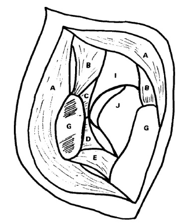
Figure 6. Line Diagram to show that the Osteotomy is completed and the flap retracted, after incising the capsule to expose the Hip Joint, (Courtesy: Reproduced with the kind permission of Injury/Elsevier).
Line diagram showing the following structures: A: Gluteus maximus; B: Gluteus medius; C: Piriformis; D: Triradiate tendon; E: Quadratus femoris; G: Greater trochanter; I: Acetabulum; J: Femoral head.
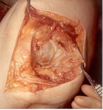
Figure 7. Hip Joint opened (Courtesy: Photograph reproduced with the kind permission of Injury/Elsevier).
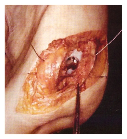
Figure 8. Wiring of the trochanteric fragment (Courtesy: Photograph reproduced with the kind s permission of Injury/Elsevier).
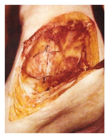
Figure 9. Hip Joint reconstituted (Courtesy: Photograph reproduced with the kind permission of Injury/Elsevier).
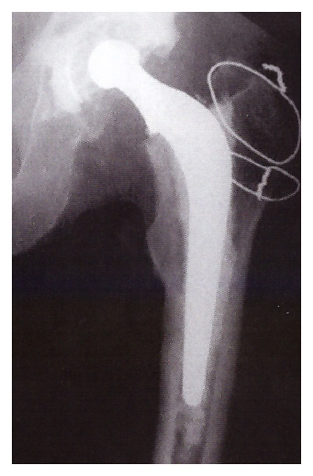
Figure 10. Radiograph of total Hip prosthesis (Courtesy: Radiograph reproduced with the kind permission of Injury/Elsevier).
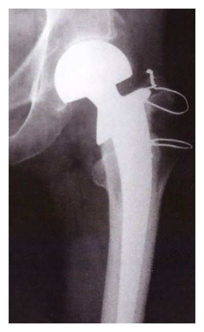
Figure 11. Radiograph of Bipolar prosthesis (Courtesy: Radiograph reproduced with the kind permission of Injury/Elsevier).
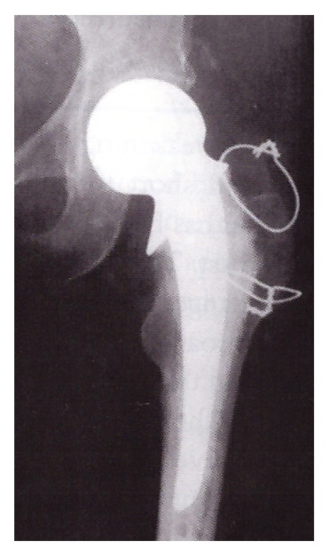
Figure 12. Radiograph of Thompson’s hemi-arthroplasty (Courtesy: Radiograph reproduced with the kind spermission of Injury/Elsevier).