Abstract
The concept of “Analogue” means continuous, as opposed to digital which is either on or off. Compared to the analogue concept which includes everything that is real in the entire Universe we can see, touch, taste, smell or change from one form to another, the digital entity is only a virtual existence. Digital is what it is and bears no relationship to the real world other than electronic switching from one state to another, i.e., an ON state or an OFF state. Digital processing has nothing whatsoever to do with either water or the nanometre sized silver clusters electrically suspended therein. This paper will present a number of analogue based electro-optical strategies and ideas for testing the many aspects and characteristics of such silver nanosized collections of atomic clusters in their aqueous suspensions. A further benefit offered by analogue technologies is due to the continuous and uninterruptable existence that is nevertheless subject to the always present concept of Change and Entropy.
Key words
analogue, digital, Ohm’s Law, capacitive reactance and cross polarised light scattering spectral-photometrics
Introduction
During initial experimentation with so-called colloidal silver in 2008, it was soon realised that what was then known as a dispersion of colloidal silver nanoparticles was in fact an electrical suspension of collections of nanometre sized atomic silver clusters. When assessing properties of this material and commercial pure water, issues with digital instruments led to anomalies being identified and thus to the development of entirely new approaches. Most of these anomalies with digital equipment arose out of the principle of operation that included sampling instead of measuring and the use of resistive shunts at low impedances incomparable with the high dielectric properties of water. As an example, digital multimeters generally do not exceed an input resistance of more than 10 to 40 million ohms with an exception of one specific a digital multimeter boasting an input resistance factor of 200 million ohms (200 MOhm for short). Compared to that, a common Vacuum tube voltmeter (VTVM) used by TV technicians in the middle of the 1900’s had an upper limit of some 1,000 M-Ohms resistance capability.
Problems in testing water used in the production of atomic silver suspensions
Impedance or Input resistance mismatching
Impedance effects at alternating current (AC) are frequency dependent, only direct current (DC) remains unaffected and is better referred to as DC input resistance. Such DC input resistances can be as high in some semiconductors as 1.5 Tera Ohm. One Tera Ohm is 1012 Ohm, which equals 1 million- million Ohm. Water is a dielectric material, and when there is an absence of ions and contaminants, it presents a very high direct current (DC) resistance, so that only a very low current (in the order of pico amperes (10-12) will flow [1-4]. Digital conductance meters apply alternating current (AC), which presents a different impedance at different frequencies (e.g. at 500 Hz or 3,000 Hz). (Figure 1 and 2)
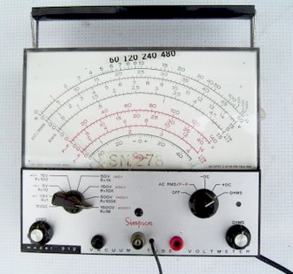
Figure 1. A typical vacuum tube voltmeter. The scale for resistance increases to the right and diminishes towards the left, which is opposite way to analogue multimeters. On this unit, the far right is a maximum value of 1,000 million Ohms.
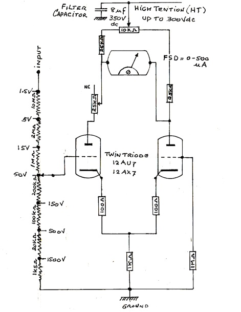
Figure 2. Simplified schematic of a Vacuum Tube Voltmeter circuit. It consists of a high-tension power supply, a low voltage AC supply (12.6 volts), a twin triode vacuum valve, a 500-micro ampere meter, a variable resistor for setting bias, and other resistors, some of which are used as a voltage divider. Compared to a transistorized voltmeter which has an average impedance at the input of 10 kilo Ohm, the VTVM offers an n input resistance at least a hundred times higher. The reason for this is that there is no actual connection between the grid (small dashed lines) and the plate at the top of valve.
Resistive loading
Loading of Instrumentation occurs with low input DC resistances and an effect named ‘parallel resistance’ which is ever present. In order to deal with the effects of such parallel resistance, the input resistance of a measuring instrument must be substantial higher by a factor of at least 1,000 in order to minimize incorrect readings errors. In the past to reduce such errors in electronic circuitry, the vacuum tube voltmeter (VTVM) was used. Such meters can show full scale deflection (FSD) at 1,000 million Ohms and is technically acceptable for measuring high value potentiometer resistors at 10 million Ohm. Such high resistance values have been verified by using equivalent value 1% tolerance precision resistors measured on the bench. Thus, if a resistor or a sample of purified water had a real DC resistance of 100 million Ohm, using a 100 million Ohm input resistance meter would give a 50% error due to loading, i.e., 100 MOhm in parallel with 100 MOhm is 50 MOhm. Subsequently a meter with 1,000-million-ohm resistance would have an error of only 10% and the higher the input resistance of the measuring instrument the smaller would be the error created. However, when measuring a resistor of 200 million Ohms on the bench, none of six different makes of digital multimeters could provide a resistance reading. The use of digital multimeters for such work is inherently flawed. Instead, precision resistance measuring techniques using analogue equipment with high input impedance are essential. The resistance measurement range of such analogue technology extends into the Tera Ohm region [1].
Electrochemical effects of water
Because no salts or other chemistry are involved other than pure silver, direct current and commercial pure water, the procedure is electrochemical and not electrolytic. When DC voltages applied across the probes exceed the equilibrium voltage of water (1.23 volt), water molecules break up into hydrogen and oxygen gasses. This threshold was originally stated as being at 1.25 volts by Michael Faraday in the early 1800’s, but has since been more accurately assessed as being 1.23 volt.
Electrode separation
The resistance of water is directly related to the volume of the water and to a lesser extent the separation of the electrodes. An experiment was conducted using a tank measuring 1,200 × 200 × 200 mm which contained approximately 48 litres of deionised water. Two 150 mm long electrodes of 3 mm diameter were placed 1,000 mm apart. A VTVM was used to measure the resistance of the water. At 1,000 mm separation of the electrodes, the meter reading was 1,000 million Ohms, but this lowered as the electrodes were brought closer together, such that at an electrode separation of 400 mm the reading had dropped to 300 million Ohms. Using a probe fitted with two opposing silver foils measuring 10 × 10 mm square and separated by 10 mm placed in the tank also gave a VTVM reading of 300 million Ohms (Figure 3).
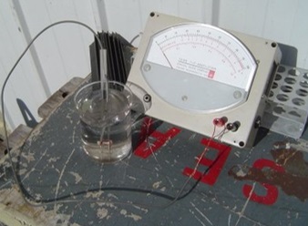
Figure 3. Prototype high impedance water purity tester and probe.
Non-linear current flow
The flow of current through liquid water does not appear to follow a straight path from cathode to anode as one would expect, but instead follows a path several times longer than the electrode separation distance. If the water is held in a metal tank it may follow a current trajectory via the inner walls of the tank, not unlike the concept of resistivity measurement per centimeter (cm) with solid conductors where current flows predominantly on the outside of the conductor between two opposing surfaces. Another reason why current flowing in water could deviate from the shortest distance between two points is the formation of matrices (making and breaking of Hydrogen bonds) as well as the hydrogen atoms as part of the water molecule orientating themselves towards hydrated electrons. It is possible to see such matrices form, by illuminating low concentration solutions of nano-sized atomic silver clusters with a 405-nm wavelength violet light from light emitting diodes (LEDs) and observing the solution over time, where a standing wave pattern appears (Figure 4 and 5) under illumination but disappears slowly when the light source is removed.

Figure 4. Standing wave patterns of scattered light in water with silver nanoparticles illuminated with a single 405 nm LED.
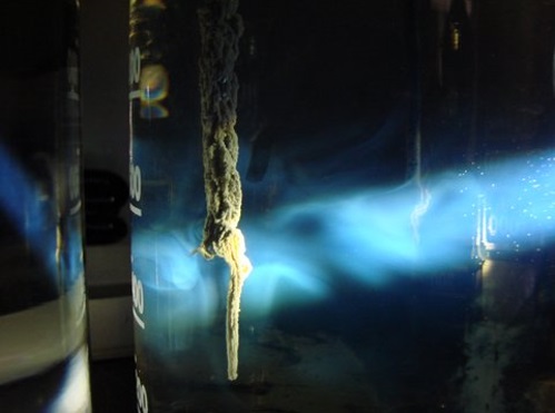
Figure 5. Illumination of water with silver nanoparticles using a white light source, showing colourful light scattering patterns. There is silver oxide present on the silver cathode.
Conductivity measurements
It has been common practice to measure the dielectric properties of water with the concept of “conductance as the reciprocal of resistivity over a specific distance”, i.e., per cm. This conductance measurement was given the name Siemen, after the name of Werner von Siemen, who designed a standard of Ohmic resistance for copper telegraph paper in the late 1880’s. He coined the term. Some years later, it was used to measure the conductance/resistivity of water, when the earlier expression of Mho (the reversal and reciprocal of Ohm) lost its popularity. Siemen at 0.95 Ohm was too large a value to be used for pure water, so the milli Siemen and micro Siemen (mS and uS) were found to be more suitable. In all its way, Conductance in particular, needed to be consistent with Ohm Law because of the insistence of the reciprocal of resistivity and as such 1 micro Siemen/cm was held to be equal to a resistivity of 1 million Ohm/cm. From that was concluded that from that basic concept it would follow that 0.1 uS/cm would be equal to 10 MOhm/cm for purer water and 10 uS/cm would equate to 100,000 Ohm/cm for a lesser pure water. It would seem that historically this assumed reciprocity between uS/cm and Ohm/cm has never been verified to be correct. With only digital multimeters in use how could that have been done anyhow when the conductance of pure and ultrapure water reaches 0.1 uS (10 MOhm) and 0.01 uS (100 MOhm) respectively. These shortcomings certainly point the way to the introduction of more precise analogue instrumentation. A recent test is an example of confusion, when measuring the conductance of a sample of commercial distilled water at 1 uS/cm. such a measurement would equate to a resistivity of 1 MOhm/cm but instead was found to be only 100,000 Ohm/cm. The reason soon became clear, the water was contaminated and causing a resistive loading, something not measured by the Conductance meter.
Closing note on this chapter
A valid technical and scientific argument is available to prove that alternating current measurement of water is flawed. For a start, electrolysis and electrochemistry operate on direct current (DC) only and as such should be measured that way as well. For that purpose, we have OHM’s Law, i.e., Current, (I) equals Voltage (V) divided by Resistance (R). We must also relate to the premise that Impedance relates to Alternating Current and its operating Frequency. Direct Current on the other hand is not related to Frequency at all.
The insistence of chemists to use AC Conductance for measuring the purity of water by estimating electrolytic and ionic content is seriously flawed and this error is further compounded by using the term Siemen originally used to measure the Ohmic resistance of solid metal conductors. So, by using AC Conductance to prove either a low conductance (high resistivity) or a high AC Conductance (low resistivity) was to stop the electrical polarisation of the water itself. Everything would apparently be in order but for the fact that the reciprocity of Resistivity could never be measured using AC. It is a DC component under OHM’s LAW. Only in the case of a wire wound resistor could AC create a RELUCTANCE and oppose any AC Frequencies. In conclusion, we must see AC as a Frequency dependant impedance and DC as a high or low input and/or output resistance as a proper wording under OHM’s Law.
Testing the properties of colloidal silver
There is presently no specific standard for what constitutes a high grade of colloidal silver [5]. The most likely reason for this shortcoming is the varied range of production methods used worldwide, and a limited understanding of the material itself. A preparation of colloidal silver should be just that, with no other ions (including ionic silver), and not containing dangerous contaminants such as arsenic and/or lead. In addition, the preparation must be stable, with a large negative Zeta potential, a small cluster size, and a corresponding narrow distribution, i.e., 3.6 to 10.1 nm with the largest atomic clusters being between 5 and 7 nm).
The colloidal silver produced by the author contains nanometre sized atomic silver clusters, in the range of 10 nm and smaller. At that size range, quantum effects occur. Such nanometre sized clusters are generated by an electro-photochemical production method without the use of any other chemistry. The end product is far more stable than those produced using other methods [5]. The production methodology can be summarized as follows: Two silver electrodes are placed some distance apart and suspended in a tank filled with deionised water. The water is subjected to a high voltage potential (300 volts DC). This will ensure uninterrupted current flow of 500 microamperes in pure water [5]. Doubling the voltage to 600 volts DC will allow current flow up to 1500 microamperes, a threefold increase. As the ionic silver is produced from the metallic bulk silver, the simultaneous irradiation by violet light changes the ionic silver into neutral silver atoms that seek stability by forming valence electron protected atomic clusters. Such a methodology has been found to be very stable for many years [5]. For the benefit of this material too, new methodologies using analogue testing facilities have to be created.
Testing for concentration
As part of a ‘to be introduced protocol’, the concentration of the neutral silver clusters has to be determined. This is an essential part when establishing the Minimum Inhibitory Concentration (MIC). This is a required strategy for determining the smallest amount of the material that will do the job. It is most unfortunate that existing protocols for concentrations of nanometre sized atomic clusters like dilution practices, do not lend themselves for this substance. Instead it would be prudent to produce this substance at precise concentration levels, i.e., 2 ppm, 5 ppm, 10 ppm etc. The most technically advanced analyser for concentration would be an Inductively Coupled Plasma Mass Spectrophotometer or ICP-MS. Its inability to distinguish between ionic silver, neutral silver and other silver compounds make this nevertheless an unsuitable instrument. In this case too, analogue electronics by way of Capacitive Reactance can tell actual concentration levels from 1 ppm to 100 ppm in seconds.
Testing for other aspects of nanometre sized atomic silver clusters
The most common remaining characteristics of nanometre sized atomic silver clusters are:
(a) Cluster size, shape, and size distribution.
(b) Zeta potential for determining the stability of the substance. The higher the negative potential is, the higher is the repulsion and as a direct consequence its stability.
(c) The level of contamination by dangerous substances.
To examine silver clusters by scanning electron microscopy, they must be dried onto a substrate, which causes them to aggregate. In this state, they are no longer in their normal state but have reverted back into a metal.
Dynamic light scattering and laser diffraction
A number of optical techniques have been employed for characterizing nanoparticles, including dynamic light scattering and laser diffraction. Current manufacturers of particle sizing equipment state that the data produced are an ‘approximation’ since they are generated using proprietary algorithms. Since it is claimed that silver reflects at least 97% of all visible light (400 to 700 nm), the remaining 3% could be refracted. Most likely this will be some small percentage at the longer wavelengths of visible red light, and the remainder at 420 nm where silver is known to absorb that wavelength.
Suggested analogue instrumentation for characterising nanometre sized silver particles in suspension
Extremely high impedance DC current meter
This device measures the dielectric properties of water-based materials using Ohms Law, over a fixed distance of 10 mm. Under Ohms law, voltage equals current times resistance. At very low voltages, for resistance values in the hundreds of millions of Ohms, very low currents will be present in the order of pico amperes (10-12) to nano amperes (10-9) To measure such low currents requires very sensitive instrumentation with very high input resistances, so as not to load the water sample via the parallel resistance phenomenon. It is well known that the resistance of resistors in parallel is always less than their individual values. To reduce the parallel resistance effect, a device was constructed which has an input impedance of 10,000 million Ohm, so that any loading of the water can be considered negligible. To avoid breakdown of water, this device applies a potential across the sample of no more than 1.0-volt DC. An analogue readout is taken from a moving coil panel meter with a full-scale deflection (FSD) of 100 microamperes. A probe made from acrylic resin is fitted at the end with two small flat pieces of silver sheet 10 × 10 mm which are spaced 10 mm apart. The probe is inserted into the water and used to measure resistance, which will be lower when more ions are present. Relatively pure water reads around 2 microamperes, while fresh tap water gives readings 70 to 90 microamperes. The response time is 1 second or less.
Cross polarising and light scattering spectrophotometer
Since silver particles (like those of some other metals e.g. aluminium) are good reflectors of visible light and display little or no refraction of light (unlike water or glass). Cross polarization of the incident light can be employed in their detection, so that only the scattering of light from silver cluster is seen and measured using an appropriate photo-sensor. By altering the wavelength of the incident light using a diffraction grating, the effect of wavelength on scatter can be assessed. Very small (nanometre sized) silver clusters will absorb violet light at wavelengths around 420 nm, so there will be no reflection. This provides proof that the particles are silver [6,7].
Capacitive reactance measurement device
When measuring the DC capacitance of two opposing electrodes in relatively pure water, a reading is obtained in the picofarad range (10-12). If, however if nanometre sized atomic silver clusters are introduced into the water the capacitance of the two plates increases with concentration. The range of measurement is from Pico farads (10-12) at low concentrations to nano farads (10-9) for high concentrations Most digital capacitance meters lack the sensitivity to measure these changes, but specially designed analogue electronic bridge based instruments can. Such instruments can be used to measure silver concentrations from 1 to 100 ppm.
Shadow casting instrument
To examine particles in situ, the shadow casting principle can be used. The closer the incident light is to a particle in water, the larger the shadow that is created. Conversely, the further the incident light is from the subject, the smaller the shadow will be. Nanometre clusters that are far below micron size cannot be observed with standard optical microscopy. A light source with adjustable distance which casts shadows using either violet or ultraviolet light for high resolution, may allow photographic recordings of silver clusters in situ. The concept of nanoscale measurement using this approach is based in part on the Foucault method for testing the optical properties of astronomical parabolic telescope mirrors using parallel light. Such techniques are capable of detecting variation levels in curvature as small as 1/1,000,000 of an inch. Compared to a micron, that would be about 40 times smaller (25 nm) and is certainly worthy of investigation. Unlike the testing of telescope mirrors which uses incandescent light, the approach for atomic silver the shorter wavelength violet and ultraviolet light would be used and this should promise a much of higher resolutions. Such a light source would take the trajectory of a folding and unfolding after reflection of the beam over a distance of 4 meter (2 times double the focal length) and return to the starting point over a total distance within 200 mm from where it started.
Conclusion
The properties of water and nanometre sized atomic silver are complex. Because of a range of issues with current digital instrumentation, a number of analogue instruments have been designed and prototypes instruments constructed in order to assess ultrapure water and the nano silver contained therein. These instruments have proven to operate as expected. Those working with ultrapure water and suspended atomic silver need to be very discerning in their choice of equipment used to determine their electrical and optical properties.
References
- Bevilaqua AC. Ultrapure water -The standard for resistivity measurements of ultrapure water. 1998 Semiconductor Pure Water and Chemicals Conference
- Malmberg CG, Maryott AA (1956) Dielectric constant of water from 00 to 1000 C. Journal of Research of the National Bureau of Standards 56: 1-8.
- Pérez C, Muckle MT, Zaleski DP, Seifert NA, Temelso B, et al. (2012) Structures of cage, prism, and book isomers of water hexamer from broadband rotational spectroscopy. Science 336: 897-901. [Crossref]
- Pollack GH. The fourth phase of water. Beyond solid, liquid and vapor. Seattle: Ebner & Sons.2013.
- Laroo H (2013) Colloidal nano silver – Its production method, properties, standards, and its bio-efficacy as an inorganic antibiotic. J Phys Chem Biophys 3: 130.
- Gryczynski Z, Lukomska J, Lakowicz JR, et al. (2006) Depolarised light scattering from silver nanoparticles., Chem Phys Lett 421: 189-192.
- Stamplecoskie KG, Scaiano JC (2010) Light emitting diode irradiation can control the morphology and optical properties of silver nanoparticles. J Am Chem Soc 132: 1825-1827. [Crossref]
- Wayne RP. Photochemistry. London: Butterworths 1970: 242-249.
- Cock I, Mohanty S, White AR, Whitehouse M (2012) Colloidal silver (CS) as an antiseptic. Two opposing viewpoints. Pharmacog Communic 2: 47-56.